Definitions
Length overall (LOA)
Length of water line (lwl)
Length between perpendiculars (LFF)
Rated length
he hull of a yacht is a complex three-dimensional shape, which cannot be defined by any simple mathematical expression. Gross features of the hull can be described by dimensional quantities such as length, beam and draft, or non-dimensional ones like prismatic coefficient or slenderness (length/displacement) ratio. For an accurate definition of the hull the traditional lines drawing; is still a common tool, although most professional yacht designers now take advantage of the rapid developments in CAD introduced in Chapter 1.
In this chapter we start by defining a number of quantities, frequently referred to in yachting literature, describing the general features of the yacht. Thereafter, we will explain the principles of the traditional drawing and the tools required to produce it. We recommend a certain work plan for the accurate production of the drawings and, finally, we show briefly how the hull lines are generated in a modern CAD program.
The list of definitions below includes the basic geometrical quantities used in defining a yacht hull. Many more quantities are used in general ship hydrodynamics, but they arc not usually referred to in the yachting field. A complete list may be found in the International Towing Tank Conference (ITTC) Dictionary of Ship Hydrodynamics.
The maximum length of the hull from the forwardmost point on the stem to the extreme after end (see Fig 3.1). According to common practice, spars or fittings, like bowsprits, pulpits etc are not included and neither is the rudder.
The length of the designed waterline (often referred to as the DWL).
This length is not much used in yachting but is quite important for ships. The forward perpendicular (FP) is the forward end of the designed waterline, while the aft perpendicular (AP) is the centre of the rudder stock.
The single most important parameter in any rating rule. Usually L is obtained by considering the fullness of the bow and stern sections in a more or less complex way.
The maximum beam of the hull excluding fittings, like rubbing strakes.

Fig 3.1 Definitions of the main dimensions
Beam of waterline (bwl)
Displacement
The maximum beam at the designed waterline.
The maximum draft of the yacht when floating on the designed waterline. Tc is the draft of the hull without the keel (the 'canoe' body).
The vertical distance from the deepest point of the keel to the sheer line (see below). Dc is without the keel.
Could be either mass displacement (m) ie the mass of the yacht, or volume displacement (V or V), the volume of the immersed part of the yacht. mc, Vc and Vc are the corresponding notations without the keel.
Midship section For ships, this section is located midway between the fore and aft perpendiculars. For yachts it is more common to put it midway between the fore and aft ends of the waterline. The area of the midship section (submerged part) is denoted AM, with an index 'c' indicating that the keel is not included.
Maximum area section For yachts the maximum area section is usually located behind the midship section. Its area is denoted Ax (AXc).
Prismatic coefficient This is the ratio of the volume displacement and the maximum section (CP) area multiplied by the waterline length, ie CP = V/(AX • Lwl). This value is very much influenced by the keel and in most yacht applications only the canoe body is considered: CPc = Vc(AXc • Lwl). See Fig 3.2. The prismatic coefficient is representative of the fullness of the yacht. The

Circumscribed cylinder volume = v = L^ Ay
Fig 3.2 The prismatic coefficient

BOX WL WL c
Circumscribed box volume =
Fig 3.3 The block coefficient
Block coefficient ( CB)
Centre of buoyancy (B)
Centre of gravity (G)
Freeboard fuller the ends, the larger the Cp. Its optimum value depends on the speed, as explained in Chapter 5.
Although quite important in general ship hydrodynamics this coefficient is not so commonly used in yacht design . The volume displacement is now divided by the volume of a circumscribed block (only the canoe body value is of any relevance) CBc = V J(Lwl • BWL • Tc). See Fig 3.3.
The centre of gravity of the displaced volume of water, its longitudinal and vertical positions are denoted by LCB and VCB respectively.
The centre of gravity of the yacht must be on the same vertical line as the centre of buoyancy. In drawings G is often marked with a special symbol created by a circle and a cross. This is used also for marking geometric centres of gravity. See. for instance, Figs 5.27 or 8.2.
The intersection between the deck and the topside. Traditionally, the projection of this line on the symmetry plane is concave, the 'sheer* is positive. Zero and negative sheer may be found on some extreme racing yachts and powerboats.
The vertical distance between the sheer line and the waterline.
Tumble home
When the maximum beam is below the sheer line the upper part of the topsides will bend inwards (see Fig 3.4). To some extent this reduces the weight at deck level, but it also reduces the righting moment of the
Fig 3.4 Definition of tumble home and flare

Tumble home crew on the windward rail. Further, the hull becomes more vulnerable to outer skin damage in harbours.
Flare The opposite of tumble home. On the forebody in particular, the sections may bend outwards to reduce excessive pitching of the yacht and to keep it more dry when beating to windward.
Scale factor (a) This is not a geometrical parameter of the hull, but it is very important when designing a yacht. The scale factor is simply the ratio of a length (for instance the Lw,) at full scale to the corresponding length at model scale. Note that the ratio of corresponding areas (like the wetted area) is a2 and of corresponding volumes (like displacement) a3.
Lines drawing A complete lines drawing of the YD 40 is presented in Fig 3.5. The hull is shown in three views: the profile plan (top left), the body plan (top right) and half breadth plan (bottom). Note that the bow is to the right.
In principle, the hull can be defined by its intersection with two different families of planes, and these are usually taken as horizontal ones (waterlines) and vertical ones at right angles to the longitudinal axis of the hull (sections). While the number of waterlines is chosen rather arbitrarily, there are standard rules for the positioning of the sections. In yacht architecture the designed waterline is usually divided into ten equal parts and the corresponding sections are numbered from the forward perpendicular (section 0) backwards. At the ends, other equidistant sections, like # 11 and # 1 may be added, and to define rapid changes in the geometry, half or quarter sections may be introduced as well. In Fig 3.5 half sections are used throughout.
The profile is very important for the appearance of the yacht, showing the shapes of the bow and stern and the sheer line. When drawing the waterlines, displayed in the half breadth plan, it is most helpful if the lines end in a geometrically well defined way. Therefore a 'ghost" stem and a 'ghost' transom may be added. The ghost stem is the imagined sharp leading edge of the hull, which in practice often has a rounded stem, and the ghost transom is introduced because the real transom is often curved and inclined. If an imagined vertical transom is put near the real one at some convenient station, it will facilitate the fairing of the lines. The drawing of Fig 3.5 has been produced on a CAD system and no ghost stem is shown. However, a ghost transom is included.
In the body plan, the cross sections of the hull are displayed. Since the hull is usually symmetrical port and starboard, only one half needs to be shown, and this makes it possible to present the forebody to the right and the afterbody to the left. In this way mixing of the lines is avoided and the picture is clearer. Note that in the figure the half stations are drawn using thinner lines.
The above cuts through the hull are sufficient for defining the shape, but another two families of cuts are usually added, to aid in the visual perception of the body. Buttocks are introduced in the profile plan,

* * ^ "i * 2 § 2 II II II II II II II ll II
showing vertical, longitudinal cuts through the hull at positions indicated in the half breadth plan. The diagonals in the lower part of the half breadth plan are also quite important. They are obtained by cutting the hull longitudinally in different inclined planes, as indicated in the body plan. The planes should be as much as possible at right angles to the surface of the hull, thus representing its longitudinal smoothness. In practice, the flow tends to follow the diagonals, at least approximately, so that they are representative of the hull shape as "seen' by the water. Special attention should be paid to the after end of the diagonals, where knuckles, not noticcd in the other cuts, may be found, particularly on lOR yachts from the 1970s and the 1980s. Almost certainly, such unevenncss increases the resistance and reduces the speed of the yacht.
The other line in the lower part of the half breadth plan is the curve of sectional areas, representing the longitudinal distribution of the submerged volume of the yacht. The value at each section is proportional to the submerged area of that section, while the total area under the curve represents the displacement (volume). A more detailed description of the construction of the curve of sectional areas will be given in Chapter 4.
In order to define exactly the shape of the hull a table of offsets is usually provided by the designer. This is to enable the builder to lay out the lines at full size and produce his templates. Offsets are always provided for the waterlines, but the same information may be given for diagonals and/or buttocks also. Note that all measurements are to the outside of the shell.
The drawing should be made on a special plastic film, available in different thicknesses. The film is robust and will not be damaged by
Photo 3.6 Tools (triangle, plastic film, straight edge, brush, pens, pencil, erasing shield and eraser)

Photo 3.7 Tr¿\nster of measures from body plan (top) to half breadth plan (bottom) using a paper ribbon

erasing. Furthermore, it is unaffected by the humidity of the air. which may shrink ordinary paper.
Since the film is transparent the grid for the lines drawing is drawn on the back so that it will remain, even after erasing the hull lines on the front many times. Great care must be exercised when drawing the grid, making sure that the alignment and spacing are correct and that all angles arc cxactly 90°. In Fig 3.5 the grid is shown as thin horizontal and vertical lines, representing waterlines, buttocks and stations.
Black ink should be used when drawing the grid and preferably when finishing the hull lines also. However, when working on the lines a pencil and an eraser are needed. There are, in fact, special pencils and erasers for this type of work on plastic film. An erasing shield and a brush are also most useful (see Photo 3.6).
For creating the grid a long straight edge is required, together with a
Photo 3.8 Ducks and a spline used for drawing a water Iine

Photo 3.9 Templates used for drawing lines with large curvature

large 90° set square. It is very convenient to have a bunch of paper ribbons, which can be used for transferring different measures from one plan to the other. For example, when drawing a waterline the offsets of this line may be marked on the ribbon directly from the body plan and moved to the half breadth plan (Photo 3.7).
To draw the hull lines it is necessary to have a set of splines and weights or ducks. Long, smooth arcs can be created when bending the splines and supporting them by the ducks at certain intervals. Photo 3.8 shows how these tools are used when drawing a waterline. The splines should be made of plastic, somewhat longer than the hull on the drawing, and with a cross-section of about 2.5 mm2. Many different types of ducks can be found, some of them home made. Preferably,

Photo 3.10 PI an i meter they should be made of lead, and the weight should be between 1.5 and 2.5 kg. To be able to support the spline, they should have a pointed nose, as shown in Photo 3.8.
The splines are needed when drawing the lines in the profile and half breadth plans. However, the lines of the body plan are usually too curved for the splines, so it is necessary to make use of a set of templates especially developed for this purpose. The most well known ones are the so called Copenhagen ship curves, the most frequently used of which are shown in Photo 3.9.
A very convenient instrument, well known in naval architecture, is the planimeter, used for measuring areas (see Photo 3.10). The pointer of the planimeter is moved around the area to be measured, and the change in the reading of the scale when returning to the point of departure gives the area enclosed by the path followed. Considering the difficulty in following exactly any given line the accuracy is surprisingly high, more than adequate for the present purposes. The need for measuring areas will be explained in the next chapter.
Since many calculations have to be carried out when preparing the drawings, and indeed in the whole design process, an electronic calculator is essential. A simple one would be sufficient in most cases, but a programmable calculator would simplify some of the calculations, particularly if a planimeter is not available. Most scientific calculators have programs for calculating areas with acceptable accuracy, and programs are available for most of the calculations described in the next chapter.
Designing the hull is a complex process, and many requirements have to be considered. One difficulty is that important parameters, such as the displacement cannot be determined until the lines have been fixed. This calls for an iterative method. Such a method is also required in the fairing of the lines. The problem is to make the lines in one projection correspond to smooth lines in the other two projections. For an inexperienced draftsman this problem is a serious one, and many trials may be needed to produce a smooth hull.
While the preferred sequence of operations may differ slightly between yacht designers the main steps should be taken in a certain order. In the following, we propose a work plan, which has been found effective in many cases. It should be pointed out that the plan does not take into account any restrictions from measurement rules.
Step 1: Fix the main dimensions These should be based on the general considerations discussed in Chapter 2, using information on other yachts of a similar size, designed for similar purposes. This way of working is classical in naval architecture, where the development proceeds relatively slowly by evolution of previous designs. It is therefore very important, after deciding on the size of the yacht, to find as much information as possible on other similar designs. Drawings of new yachts may be found in many of the leading yachting magazines from all over the world.
The dimensions to fix at this stage are: length overall, length of the waterline, maximum beam, draft, displacement, sail area, ballast ratio, prismatic, coefficient and longitudinal centre of buoyancy. One of the aims of this book is to help in the choice of these parameters and to enable the reader to evaluate older designs when trying to find the optimum for his own special demands.
Step 2: Draw the profile As pointed out above, this step takes much consideration, since the aesthetics of the yacht are, to a large extent, determined by tBfe pi^ffle-
Step 3: Draw the midship section The midship section can be drawn at this stage, or, alternatively, the maximum section if it is supposed to be much different. This may occur if the centre of buoyancy is far aft. The shape of the first section drawn is important, since it determines the character of the other sections.
Step 4: Check the displacement To find the hull displacement calculate (or measure) the submerged area of the section just drawn and multiply by the waterline length and the prismatic coefficient chosen for the hull. From the ballast ratio, the keel mass can be computed and the volume can be found, dividing by the density of the material (about 7200 kg/m3 for iron and 11300 kg/m- for lead). Assume that the rudder displacement is 10% of that of the keel and add all three volumes. If the displacement thus obtained is different from the prescribed one, return to step 3 and change accordingly.
The procedure described is for a fin-keel yacht. For a hull with an integrated keel, as on more traditional yachts, the prismatic coefficient usually includes both the keel and the rudder.
Step 5: Draw the designed waterline One point at or near the midship station is now known, together with the two end points from the profile, so now a first attempt can be made to draw the designed waterline.
Step 6: Draw stations 3, 7 and the transom The waterline breadth is now known, as well as the hull draft, and the sections should have a family
resemblance to the midship section. Often it is helpful to draw a ghost transom behind the hull.
Step 7: Draw new waterlines Two or three waterlines can now be drawn above and below the DWL. If the appearance is not satisfactory, go back to step 6 and change.
Steps 8 and 9: Add new sections and waterlines
Once this is done, sections I-9 should be completed as well as 7-10 waterlines. Constant adjustments, have to be made in order to create smooth lines in the body plan, as well as in the half breadth plan.
Step 10: Recheck the displacement and the longitudinal centre of buoyancy The curve of sec tional areas can now be constructed. Its area gives the displacement (excluding that of keel and rudder) and its centre of gravity corresponds to the longitudinal position of the centre of buoyancy. If not correct, adjustments have to be made from steps 5 or 6,
Step 11: Draw diagonals Inspect the smoothness, particularly near the stern. Adjust if necessary.
Step 12: Draw buttocks This is the final check on the smoothness. Usually only very minor corrections have to be made at this stage.

Computer aided design of hulls
As mentioned in Chapter 1, most CAD programs use master curves for generating the hull surface. Each curve is defined by a number of points, called vertices. Photo 3.11 shows, in a plan view, the grid of master curves used for generating the YD-40 hull. One of the transverse curves has been selected in Photo 3.12 and it can be seen how the smooth hull surface is generated inside the curve, which is shown as piece-wise linear between the vertices.
Photo 3.11 Grid of master curves used for the YD-40 (the vertical line to the right marks the origin of the coordinate system)
Photo 3.12 A section with vertices (crosses), master curve (between the crosses), hull surface and cuwature (outermost line)

The task of the designer is to specify the vertices in such a way that the desired hull shape is created.There are different ways of achieving this. Some programs start from a long cylindrical body or a box, while others start from a flat rectangular patch, defined by an orthogonal grid. These original shapes are then distorted by moving the vertices around, and it is relatively easy to produce a yacht-like body. However, it takes experience and experimentation to obtain a shape that satisfies criteria set up beforehand. In practice, designers very seldom start from scratch, but work from earlier designs, which already have a desirable shape and a known grid of master curves surrounding it. Since most new designs are evolutions of previous ones this approach is very natural.
A problem encountered when the first CAD programs for yachts appeared was that the scale on the screen was too small, and the resolution too low to enable the designer to create fair lines. Small bumps on the surface could not be detected 011 the screen, and it sometimes happened that the bumps were noticed only after the start of the hull construction . Therefore the CAD program developers introduced plots of the curvature of lines on the hull. Such a plot is shown.in Photo 3.12. The curvature of the line, which essentially corresponds to a section, is almost constant, except at the ends where it goes to zero.
Photo 3.13 illustrates the sensitivity of the curvature to small changes of the surface. The sheer line is shown in a plan view. In the top photo (the real design) the curvature is smooth and relatively constant along the hull. In the bottom photo one vertex point has been moved 10 mm at full scale perpendicular to the surface. The resulting change in the sheer line is so small that it cannot be detected by eye, but the curvature exhibits a considerable bump and some smaller fluctuations, showing that the line is not smooth. By looking at the curvature, lines may thus be generated that look fair even at full scale.
Photo 3.13 Sheer line with vertices and curvature. (top) Real design. (bottom) One vertex point moved 10 mm

Photo 3,14 Perspective view A great advantage of most CAD programs is that the hull may be of the YD-40 shown in perspective. As pointed out in Chapter 1 it is important to study the sheer line in particular from different angles, since the impression of the hull contour in reality is also influenced by the beam distribution, which is not visible if only the profile view is studied. Fig 3.14 shows the YD-40 in perspective, and a good impression can be obtained of the shape. "
By using a CAD program a fair hull can be produced rapidly and different requirements may be satisfied without too much work, such as a given prismatic coefficient or longitudinal centre of buoyancy. Meeting such requirements accurately in a manual process is extremely time consuming, so it is understandable that CAD techniques are always used nowadays by professional designers. However, due to the considerable cost of a CAD system, most amateur designers will still have to use the manual approach described above.
Continue reading here: Hydrostatics And Stability
Was this article helpful?
Recommended Programs

Myboatplans 518 Boat Plans

Boat Alert Hull ID History Search

3D Boat Design Software Package
Related Posts
- Methodology - Ship Design
- Plan Drawing Fregatt - Rigging
- Hull Construction - Ship Design
- Catamaran Design Guide - Catamarans Guide
- LOD and LOA - Cruising Sailboats Reference
- Hull Hydrodynamics and Design
Readers' Questions
How to figure the width to height to length of a yacht?
To figure out the width, height, and length of a yacht, you typically need to refer to the yacht's specifications provided by the manufacturer, yacht designer, or owner. These specifications should include the appropriate measurements. Consult the yacht's specifications: Look for the official documentation or technical information provided for the yacht. This documentation usually includes the length, width, and height of the yacht, referred to as LOA (Length Overall), Beam, and Draft, respectively. The specifications are usually available in brochures, user manuals, or on the official website of the yacht manufacturer. Seek professional advice: If you cannot find the specifications yourself or need more specific information, consider reaching out to yacht brokers, yacht builders, naval architects, or other professionals in the yachting industry. They have extensive knowledge and can guide you with accurate measurements or provide information by using the yacht's model or brand. Measure the yacht yourself: If you have physical access to the yacht and cannot find the specifications through other means, you can measure it directly. However, this method is less accurate and should only be used as a last resort. Use a measuring tape or other appropriate tools to measure the overall length, width or beam, and height. Ensure to measure from fixed reference points for consistency and accuracy. Remember that yachts come in various sizes, designs, and layouts. The width or beam, for example, may be different at different points along the vessel's length due to design variations. It is essential to refer to the official specifications or seek professional advice for the most precise and reliable measurements.
Can you use geometry on boats?
Yes, geometry can be applied to various aspects of boats, particularly in the design and construction phase. Here are a few examples: Hull Design: Geometry is crucial in designing the shape and dimensions of a boat's hull. The angles, curves, and mathematical calculations are used to ensure stability, hydrodynamics, and buoyancy. Stability Analysis: Geometry is used to determine the center of buoyancy, center of gravity, and metacenter of a vessel. These calculations are essential for assessing a boat's stability, both at rest and in motion. Navigation and Bearings: Geometric concepts such as angles, triangles, and trigonometry are used to calculate headings, course corrections, and bearings while navigating a boat. Sail Measurement and Adjustments: Sailboats utilize various geometric principles to determine sail sizes, aspect ratios, and shapes. The geometry of sail adjustments, such as tightening or loosening the sail, can affect the boat's speed and performance. Nautical Charts: Geometry plays a vital role in nautical charting, which involves representing the Earth's curved surface on a flat chart. Projections, grid systems, and coordinate systems are employed to accurately depict and navigate waterways. These are just a few examples of how geometry can be applied to boats. Overall, geometry is critical in ensuring boat design, navigation, and performance, making it an important aspect of the boating industry.
How to find ship displacement from submerged area?
To find the ship displacement from submerged area, you can follow these steps: Determine the underwater or submerged area of the ship. This can be done by calculating the area of the ship's hull that is below the waterline when it is fully submerged. Convert the area into a volume by multiplying it by the ship's beam (width) or mean draft (depth). Multiply the volume by the density of the water. The density of water varies slightly depending on temperature and salinity, but a typical value is around 1,000 kilograms per cubic meter. The result of this calculation will be the ship's displacement. It represents the weight of the water displaced by the ship when it is fully submerged. Note: This method assumes that the ship's hull has a constant shape below the waterline. In reality, the shape may vary, especially towards the ends of the ship.
How to draw a simple ship?
To draw a simple ship, follow these step-by-step instructions: Start by drawing a horizontal line slightly curved at the ends to create the ship's hull. Add a smaller curved line above the hull to outline the ship's deck. At the front of the ship, draw a triangular shape for the bow. On top of the deck, draw a small rectangular structure or cabin. Add a flagpole at the back of the deck by drawing a long, thin rectangle. Draw a small rectangle or square at the top of the flagpole for the flag. Next, add a slightly curved line near the waterline for the keel of the ship. On both sides of the hull, draw a series of diagonal lines to create the ship's planking. To indicate windows or portholes, draw small oval or circular shapes along the cabin. Add a couple of mast poles on the deck. To do this, draw two vertical lines with a horizontal line connecting them at the top. On top of the mast poles, add triangular or rectangular shapes for the sails. Finally, erase any unnecessary guidelines, and you can add more details like waves or seagulls to complete your simple ship drawing. Remember, this is just one way to draw a simple ship. Feel free to modify the design or add additional elements to make it your own!
How to draw a pin keeldrawing tutorialtop keel?
To draw a pin keel, follow these steps: Begin by drawing a slightly curved horizontal line. This line will serve as the water surface. Next, draw a long vertical line that will represent the keel. The keel should start at the bottom of the water surface line and extend downward. At the bottom of the vertical line, draw a slightly curved horizontal line. This line will represent the lower part of the keel. On the left side of the keel, draw a diagonal line extending outward. This line will represent the forward part of the keel. Repeat the previous step on the right side of the keel, drawing a diagonal line to represent the aft part. Connect the ends of the diagonal lines with a curved line, forming the bottom part of the keel. Add additional detail to the keel by drawing a small horizontal line near the top. This line represents the top part of the keel. Finally, erase any unnecessary lines and add shading to give the keel more depth and dimension. Remember to take your time and practice as much as needed to improve your drawing skills.
How do you draw a ship?
Drawing a ship can be a fun and creative process. Here's a step-by-step guide on how to draw a ship: Start by drawing a long, slightly curved horizontal line in the center of your paper. This line will serve as the ship's waterline. From one end of the waterline, draw a slanted rectangle shape, slightly wider at the bottom than the top. This will be the ship's hull. At the other end of the waterline, draw a smaller rectangle shape, slightly tilted upward. This will be the ship's bow. Connect the bow and the hull with two diagonal lines, creating the ship's front structure. Add a large, slightly curved rectangle shape at the top of the hull. This will be the main deck of the ship. Draw a smaller rectangle shape above the main deck to represent the ship's superstructure. Sketch two parallel, slanted lines on the front of the ship's superstructure to create the pilot house. On the main deck, draw a few rectangular shapes to indicate windows or portholes. Add details like railing, stairs, and lifeboats on the sides and top of the ship as desired. Extend the hull below the waterline using a curved line to give the ship depth. For the finishing touches, you can draw some waves around the ship, seagulls in the sky, or a flag on top. Remember to be creative and modify the design as you like. Don't worry if your drawing doesn't turn out perfect at first; practice makes perfect!
What hull curves do yachts fallow is it x squared?
The hull curves of yachts can vary depending on the design and purpose of the yacht. While some yacht hulls may follow a curve that resembles the function of x squared, others may follow different curves such as parabolic curves, ellipses, catenary curves, or other mathematical shapes. The specific curvature of a yacht's hull is determined by factors such as the desired speed, stability, maneuverability, and hydrodynamic efficiency of the vessel. It is typically designed by naval architects and engineers who consider various factors including the size and weight distribution of the yacht, the intended use (e.g., racing, cruising, etc.), and materials used in construction. In summary, while some yachts may have hull curves similar to x squared, there is no universal standard hull curve for all yachts. The hull design depends on various factors and can incorporate different mathematical curves to achieve specific performance characteristics.
How to calculate the curvature of a boat?
To calculate the curvature of a boat, you would need to determine the radius of its curvature. The curvature refers to the degree of how much the boat's hull curves or bends. Gather the measurements: You will need the length and width measurements of the boat. These measurements can be obtained from the boat's specifications or by physically measuring it. Determine the midpoint: Locate the midpoint of the boat's length. This can be done by dividing the boat's length measurement by 2. Measure the rise: Starting from the midpoint, measure the distance between the bottom of the boat's hull and a straight line connecting the bow and stern (i.e., the rise). Measure the run: Measure the distance between the midpoint and the bottom of the boat's hull at the bow and stern. Calculate the radius of curvature: The radius of curvature can be calculated using the following formula: Radius = (run^2 + rise^2) / (8 x rise). The curvature: The curvature is calculated as the reciprocal of the radius of curvature. It's important to note that this calculation assumes a boat's hull shape can be represented by a simple section of a circle. More complex hull shapes, such as those with multiple curves or irregular shapes, may require different mathematical models or numerical methods to accurately determine curvature.
How to measure the curveture of a boat hull?
There are several methods to measure the curvature of a boat hull. Here are three common techniques: Profiling: This method involves taking measurements at specific points along the hull's surface to understand the curvature. You can use a flexible measuring tape or string to measure the distance from the hull to a straight reference line at different points along the boat's length. These measurements can then be plotted on a graph to depict the curvature of the hull. Reflection Method: For this technique, you need a laser level and a measuring tape. Firstly, position the laser level at a fixed distance from the boat hull and horizontally direct the laser beam towards the hull. The laser beam will be reflected back from the hull surface. Measure the distance from the laser level to the hull at different points along the boat's surface. These measurements can be used to calculate the curvature of the hull. 3D Scanning: Utilizing modern technology, you can use a 3D scanner to create a digital model of the boat hull. The scanner emits laser beams or projects structured light patterns onto the hull, capturing its shape in detail. The resulting 3D model can then be used to measure the curvature of the hull accurately. It is important to note that measuring the curvature of a boat hull may require specific tools and expertise. Hence, it is advised to consult with industry professionals or specialists for accurate measurements.
How to draw a yacht keel?
To draw a yacht keel, you can follow these steps: Start by drawing a horizontal line on your paper. This line will serve as the waterline. From the center point of the waterline, draw two vertical lines going downward to create the main part of the keel. These lines should taper towards the bottom. At the bottom of the keel, draw a horizontal line connecting the two vertical lines. This will form the bottom edge of the keel. Now, draw a diagonal line on each side of the keel, starting from the top and curving slightly outward. These lines will form the shape of the keel as it narrows towards the top. Connect the ends of the diagonal lines at the top with a smooth curve to create the rounded shape of the keel. Next, draw horizontal lines across the keel to represent the different sections or layers. These lines can be evenly spaced or closer together at the top and gradually getting wider towards the bottom. Add details such as ribbing or reinforcements by drawing diagonal lines across the keel, intersecting the horizontal lines. To give the keel a more realistic look, you can shade the bottom part and add some shadow where it meets the waterline. Finally, you can add additional details such as a bulbous bow or a fin at the bottom of the keel based on the specific design of the yacht you are drawing. Remember to sketch lightly at first and gradually darken your lines as you refine the shape. And don't forget to have fun and experiment with different styles and variations to make your drawing unique!
How to draw a boat into transverse stations?
Drawing a boat into transverse stations can be done by following these steps: Start by selecting a suitable scale for the drawing. This will depend on the size of the boat you want to draw and the size of the paper or canvas you are using. Begin by drawing a horizontal line across the paper, representing the waterline. Next, draw vertical lines representing the transverse stations at regular intervals along the waterline. These lines should be evenly spaced and represent the cross-sections of the boat at different points along its length. Use reference drawings or images of the boat to guide your drawing. Start by drawing the outline of the boat's hull within each station. Pay attention to the curvature and tapering of the hull as it moves towards the bow and stern. After drawing the outline, add any additional details such as deck lines, windows, hatches, and other features of the boat. Use shading techniques to add depth and dimension to the drawing. Pay attention to the light source and add shadows accordingly to create a realistic representation of the boat. Finally, go over your drawing and make any necessary adjustments or corrections to ensure accuracy.
What is nonprismatic hull?
A nonprismatic hull is a type of hull shape in naval architecture that does not conform to the standard prismatic shape of traditional sailing vessels. Nonprismatic hulls are designed to increase performance in certain areas such as speed and efficiency, as well as to reduce drag and enhance maneuverability. Nonprismatic hulls are also often used as part of a wave piercing design to cut through wave crests, thus reducing the size of the wake behind the ship.
How to design a schooner hull?
Research the history of schooner hulls and their design features. This will help you understand the shipbuilding principles and methods used in their construction. Consider the type of schooner you want to design. Is it a racing vessel or a cruising boat? This will help you determine the size, weight and other characteristics of the hull. Consider the type of material you will use for the schooner. Traditionally, schooner hulls have been made of wood or fiberglass, but there are other materials that can be used as well. You need to choose a material that meets your needs and budget. Work with an experienced maritime designer or drafter to create a 3D model of the schooner hull. This will help you visualize the hull and make sure it meets your specifications. Have a qualified shipwright or boat builder construct your schooner. Ensure that the schooner is tested and certified by a naval architect before you take it out on the water.
How to draw hull lines plan from boat existing images in reverse engineering?
Take a picture of the boat's existing lines plan. Import the image into a vector graphic program such as Inkscape, Adobe Illustrator, or Corel Draw. Trace the contours of the boat's hull using the Pen Tool or other trace tool in the program. Adjust the lines to make sure they accurately represent the boat's shape and contours. Once the lines plan is complete, use a ruler to draw perpendicular lines from the boat's existing lines plan as a reference for the hull. Use the curved line tool to refine the shape of the hull and make sure everything is in proportion and accurate. Double-check to make sure the hull lines plan is correct, and save the file for future reference.
What does half a sideways figure eight mean on a ship drawing?
Half a sideways figure eight on a ship drawing typically denotes the ship's waterline—the line where the ship sits in the water.
How to work out the shape and profile of a yatch datum line?
Establish the design criteria and parameters of the yacht. This should include the length, width, height and any other characteristics relevant to the design of the yacht. Define the design goals and objectives of the yacht, including the purpose and function of the yacht, how it will be used, and what type of sailing or other activities will take place on it. Choose an appropriate hull shape and size for the yacht based on the design criteria, goals and objectives. Create a 3D computer model of the yacht design, incorporating the appropriate hull shape and size. Use the model to define a datum line for the yacht, which will help to accurately measure the craft's performance and characteristics. The datum line should run from the center of the waterline around the hull to the transom. Using the 3D model, define the profile of the yacht by “lofting” the curves of the hull and the deck. Refine the design by adjusting the curves of the hull and deck to ensure that the yacht's performance characteristics are maximized. Use the computer model to run “virtual wind tunnel” tests on the design, to ensure that its performance characteristics are optimized.
How to draw a boat on water?
Start by sketching the basic shape of the boat. Start with a long, rectangular shape to form the hull of the boat. Add a slight curve to the top of the boat to give it an authentic boat shape. Draw a smaller rectangular shape for the cabin of the boat. Sketch two triangular shapes on the left and right side of the cabin for the sails. Draw a series of small circles along the bottom of the boat to create the waterline. Now add the details to your boat: windows, doors, life preservers, etc. Finally, draw some small waves around the boat to create the illusion of the boat sailing on water.
What are fair lines and sheer lines of a yacht?
Fair lines are the contours of the yacht's hull. Sheer lines are the long, gradual arch of the deck, starting at the bow and extending to the stern.
How to draw a hardshine boat hull quickly?
To draw a hardshine boat hull quickly, you can follow these steps: Start by drawing a horizontal line to represent the waterline. This line will serve as the base for the boat hull. Sketch a rough outline of the boat hull shape above the waterline. Keep in mind that hardshine boat hulls are typically streamlined and have a sharp, angular shape. Add a slightly curved line below the waterline to depict the bottom part of the hull. The curve should be gentle and gradually merge into the horizontal waterline. Extend two diagonal lines downward from the front end of the boat hull to create the bow. The bow should be pointed and sharp to cut through the water efficiently. Add a small transom at the rear end of the boat hull. The transom is usually flat or slightly curved upward. Sketch two straight lines from the bow to the stern to represent the deck of the boat. Draw a horizontal line across the middle section of the hull to indicate a separation or border between the upper and lower parts. Add details to the hull, such as chines (angled lines along the sides of the hull) and spray rails (small fins or ridges). These elements contribute to the boat's stability and improve its performance in the water. Shade the lower portion of the hull with a darker tone to emphasize the hardshine effect. Use quick and light strokes to achieve a glossy appearance. Finally, erase any unnecessary guidelines and refine the drawing as needed. Remember, practicing and experimenting with different techniques will help you improve your drawing skills and speed over time.
How to measure a ships hull shape from inside?
One way to measure a ship's hull shape from inside is by using 3D laser scanning. This technique uses lasers to take precise measurements of a ship's inner hull shape. The lasers scan around the interior of the ship and create a 3D image of the ship's shape. This data can then be used to create a precise and accurate measure of the ship's hull shape.
How to lay out a lines drawing for displacement hulls?
Start by drawing the waterline at the mid-point of the vessel. Draw the bow from the top of the waterline to the nose of the vessel. Draw the stern from the bottom of the waterline to the end of the vessel. Draw in all of the chines of the vessel, the curved lines along the bottom of the sides of the boat, at the waterline. Draw in any other details such as the upturned bow, the tail, or any other details that the vessel may have. Draw the sheer line and the sheer forward, running along the top of the vessel and curving inwards and downwards in the center. Add in any additional lines needed to complete the displacement hull. Use a protractor to make sure all of the angles are correct. Use a ruler to draw the exact lines and make sure the lines are the correct length.
What is Yacht Racing? (Here’s All You Need To Know)
Have you ever watched a yacht race, with its colorful sails gliding across the water in a graceful dance? Have you ever wondered what it takes to participate in yacht racing? This article will take you through all you need to know about yacht racing, from the different types of yachts and races, to sailing clubs and regattas, technical knowledge and skills, safety, and the benefits of yacht racing.
We’ll also explore some of the most popular events and races.
So whether you’re an avid sailor or just curious about this exciting sport, you’ll find all the information you need here.
Table of Contents
Short Answer
Yacht racing is a competitive sport and recreational activity involving sailing yachts .
It is most popular in areas with strong maritime cultures, such as the UK, US and Australia.
Races typically involve a course that boats must follow, which can vary in length depending on the type of race.
Competitors often use advanced sailboat designs, and use tactics and strategy to try to outmaneuver their opponents in order to be the first to cross the finish line.
Types of Yachts Used in Racing
Yacht racing can be done with a wide variety of boats, from dinghies and keelboats to multihulls and offshore racing boats.
Dinghies are small, lightweight boats with a single sail and are often used in competitive racing.
Keelboats, on the other hand, are larger and heavier boats with a fixed keel and two or more sails.
Multihulls, like the popular catamaran, are boats with two or more hulls and are designed with speed and agility in mind.
Finally, offshore racing boats are designed for long-distance racing and are typically larger and more powerful than other types of yachts.
No matter what type of yacht you choose to race, they will all have common features that make them suitable for racing.
All yachts must have a mast, sails, hull and rigging, and will usually feature a deck, compass, and navigation equipment.
Additionally, racing yachts are often fitted with safety features such as life jackets, flares, and emergency radios.
Each type of yacht has its own unique characteristics, and some are better suited for certain types of racing than others.
For example, dinghies are better suited for short-course racing, while offshore racing boats are better for long-distance racing.
Additionally, keelboats and multihulls are often used for more challenging types of racing, such as distance racing or match racing.
No matter what type of yacht you choose for racing, it is important to remember that safety should always be your first priority.
Be sure to check the weather conditions before heading out and make sure that you have the proper safety equipment on board.
Additionally, it is important to get professional instruction or join a sailing club to ensure you have the necessary skills to race safely and enjoyably.
Types of Races

Yacht racing events can take place in a wide variety of forms and formats, from long-distance ocean racing to short-course inshore racing in protected bays and estuaries.
Each type of race requires different skills and equipment, and the type of race you choose to participate in will depend on your sailing experience, budget and the type of boat you have.
Long-distance ocean racing is a popular form of yacht racing, with races often taking place over several days and often involving multiple stages.
These races often have several classes of boat competing, with each boat competing in its own class.
These races may involve sailing around a set course or route, or they may be point-to-point races, where the boats sail from one point to another.
Inshore racing is the most common form of yacht racing, with races typically taking place over a few hours or a single day.
This type of racing is often conducted in protected waters, such as bays and estuaries, and generally involves shorter course lengths than ocean racing.
Inshore races may involve multiple classes of boat, or they may be one-design classes, where all boats are the same model and size.
Multi-hull racing is another popular type of yacht racing and involves boats with two or more hulls.
These boats are generally faster and more agile than monohulls, and races are often held over a short course.
These races can be highly competitive, with teams of experienced sailors vying for position and race victory.
Offshore racing is similar to ocean racing, but often involves much longer distances and more challenging conditions.
Races may take place over several days and multiple stages, and require a high level of experience and skill.
Offshore racing boats are usually specially designed for speed and agility, and may have multiple crew members on board to help manage the boat in challenging conditions.
Sailing Clubs and Regattas
Yacht racing is a popular sport around the world, with sailing clubs and regattas held in many countries.
Sailing clubs are organizations where members can come together to race, learn, and enjoy their shared passion for the sport.
Membership in a sailing club usually includes access to the clubs facilities, equipment, and training classes.
Regattas are large-scale yacht racing events, often hosted by a sailing club.
The regatta can be organized for any type of boat, from dinghys to offshore racing boats, and the races can be held over a series of days.
The goal of the regatta is to crown the winner of the overall race, or the individual class honours.
Sailing clubs and regattas are a great way for sailors of all levels to come together and compete.
They give sailors an opportunity to hone their skills, network, and make friends with other passionate sailors.
Additionally, these events are often open to the public, so they give the general public a chance to see the amazing spectacle of yacht racing up close.
If youre looking for an exciting and fun way to get involved with sailing, look no further than your local sailing club or regatta.
Technical Knowledge and Skills

Yacht racing is a sport that requires a great deal of technical knowledge and skill.
Competitors must be familiar with the physics and dynamics of sailing, including how to read the wind and manipulate their vessel to maximize speed and maneuverability.
They must also be able to understand the principles of navigation, so they can accurately plot a course and adjust it to take advantage of the prevailing wind and current conditions.
Furthermore, competitors must be able to read the weather and use that information to their advantage in the race.
Finally, competitors need to have a good understanding of the rules of the race and how to adhere to them.
Yacht racing is a complex sport with a steep learning curve, and it requires a great deal of experience and practice to master.
Safety is a key element of yacht racing, as it involves operating large vessels in often unpredictable and hazardous conditions.
All racers must be properly equipped with the appropriate safety gear, such as life jackets, flares, and a first aid kit.
It is also essential that all racers are familiar with the rules of the race, and have a good understanding of the safety protocols that must be followed in order to ensure the safety of everyone involved.
All yacht racing events must be properly insured, and there are often medical personnel on standby in case of an emergency.
Before any race, all participants must sign a waiver declaring that they understand the risks involved and accept responsibility for their own safety.
Benefits of Yacht Racing

Yacht racing is a great way to challenge yourself and take part in a thrilling sport.
It offers numerous benefits to those that participate, from improved physical health and mental well-being to an opportunity to travel and explore new places.
Whether youre a beginner or an experienced sailor, yacht racing provides an exciting and rewarding experience.
One of the main benefits of yacht racing is its impact on physical health.
It requires a great deal of strength and endurance, as the sailors must use their arms and legs to control the boats sails and rudder.
Its also a great way to get your heart rate up and improve your cardiovascular health.
Additionally, sailing is a low-impact sport, meaning theres less risk of injury than other more strenuous activities like running or cycling.
Yacht racing also has many mental benefits.
Its a great way to relax and take in the beauty of the ocean, as well as the camaraderie and excitement of competing in a team.
Additionally, it gives sailors the opportunity to put their problem-solving skills to the test, as they must think quickly and strategize in order to succeed.
Yacht racing also requires quick decision-making, which can help to improve mental acuity and develop a more acute awareness of ones surroundings.
Finally, yacht racing is a great way to explore new places and meet new people.
Races often take place in different locations around the world, meaning sailors can get a glimpse into different cultures and explore new destinations.
Additionally, yacht racing provides an opportunity to socialize with other sailors, as well as make connections in the sailing community.
Overall, yacht racing is a great way to challenge yourself and reap the numerous physical, mental, and social benefits that come with it.
With its exciting races and stunning locations, its no wonder that yacht racing has become a popular sport around the world.
Popular Events and Races
Yacht racing is an exciting and popular sport with events and races held all over the world.
From the world-famous Americas Cup to local regattas, there are races and events of all sizes and skill levels.
The Americas Cup is the oldest and most prestigious yacht race in the world, with the first race held in 1851.
Held every 3-4 years in a different location, the Americas Cup pits the worlds best sailors against each other in a battle of boat speed, tactics and teamwork.
The Rolex Sydney Hobart Yacht Race is another major race, held annually in Australia.
The race begins in Sydney Harbour and ends in the port of Hobart, Tasmania and is known for its unpredictable and challenging conditions.
The Whitbread Round the World Race (now known as The Volvo Ocean Race) is a grueling nine-month, round-the-world yacht race.
This race is one of the most challenging and dangerous races in the world.
In addition to these larger races, there are many smaller local and national regattas and races that offer an opportunity for sailors of all skill levels to compete.
From small dinghy races to larger keelboat and offshore racing events, there are plenty of opportunities to get involved in yacht racing.
Yacht racing is a fun, competitive and rewarding sport and with so many events and races available, there is sure to be something for everyone.
Whether you are a competitive sailor or just looking to have some fun on the water, yacht racing is the perfect sport for you.
Final Thoughts
Yacht racing is an exciting and challenging sport that is enjoyed by many around the world.
With a variety of yacht types, races and events to choose from, there is something for everyone.
To get started, it is important to have a good understanding of the technical skills and knowledge needed, as well as the safety protocols associated with the sport.
With the right preparation and dedication, yacht racing can be an incredibly rewarding experience.
If you’re interested in taking up this exciting sport, make sure you check out your local sailing clubs and regattas to find out what’s on offer.
James Frami
At the age of 15, he and four other friends from his neighborhood constructed their first boat. He has been sailing for almost 30 years and has a wealth of knowledge that he wants to share with others.
Recent Posts
Does Your Boat License Expire? Here's What You Need to Know
Are you a boat owner looking to stay up-to-date on your license requirements? If so, youve come to the right place! In this article, well cover everything you need to know about boat license...
How to Put Skins on Your Boat in Sea of Thieves? (Complete Guide)
There is a unique sense of pride and accomplishment when you show off a boat you customized to your exact specifications. With Sea of Thieves, you can customize your boat to make it look like your...
- AROUND THE SAILING WORLD
- BOAT OF THE YEAR
- Email Newsletters
- Best Marine Electronics & Technology
- America’s Cup
- St. Petersburg
- Caribbean Championship
- Boating Safety
Hulls of the Modern America’s Cup
- By Mark Chisnell
- Updated: January 8, 2021
Hull design has always been the most venerated aspect of an America’s Cup yacht. The name on the drawings has often been remembered with the same reverence as that of the skipper. This might not hold for much longer because the result of the 36th America’s Cup is just as likely to be determined by the work of a systems engineer as by a naval architect.
“The hull design is one aspect of many, but it’s not the dominant aspect,” explains Martin Fischer, co-design coordinator (along with Horacio Carabelli) for the Luna Rossa Prada Pirelli Team, who is on his second America’s Cup with the Italian team. “It’s not as it was with the 12 Metre or with version five (of the International America’s Cup Class), where the hull is really almost everything.”
The rules controlling a class are always a good place to start when seeking to understand a race boat because they drive so much of the design; working for the Challenger of Record, Fischer was part of the team that wrote the class rule for the AC75 with the defenders, Emirates Team New Zealand.
In the case of the AC75, the rules, Fischer says, are actually very open. They have little to say on the structure, for instance, requiring only a “minimum areal density of any part of the hull shell” (2 kg/m²). There’s also a limit on the internal volume (at least 70 m³), and after that, much of what’s left deals with details such as water retention, fairing flaps and penetrations.
There are only a few rules that drive the hull shape and its potential performance. “There is the length,” Fischer says. “The overall length is limited to 20.6 meters (minimum, without the bowsprit), while the beam must be 5 meters. Then there are two other very important rules: There is a theoretical capsize test that is done virtually on the computer. If the boat is turned by 90 degrees, the center of buoyancy must be at a certain position.
“This rule has a strong influence on the deck shapes. You might have noticed that all the boats have relatively high freeboard; this is partly for aerodynamics, but also, if you don’t have relatively high freeboard, you don’t pass this capsize test. The next important rule is that there is a minimum requirement for the waterplane inertia.”
Er…the water what?
“If the hull is floating, then you look at the intersection of the hull with the water surface (waterplane), and that gives the surface a certain shape. And then compute the inertia of that shape (it must be at least 20 m4). It’s not important to understand exactly what it is; in the end, it is more or less a measure or a constraint on the combination of that surface and its width.”
I’m not going to try to explain the calculation of the “second moment of area”—the important thing, according to Fischer, is that you “basically cannot make an extremely narrow hull, so you have to respect a certain area for that surface, and a certain width. The rule on the inertia is also quite type-forming; it imposes widths at the waterline. Of course, we all would like [the hull] to go narrow. Especially when the boat starts going fast, just before takeoff, we all want a narrow hull. And this is why we have these humps underneath the hull.”
Ah yes, the humps, skegs or bustles are one of the most significant shared features on all four of the newly launched, second-generation AC75s. The terms refer to the narrow, protruding section that runs down the centerline underwater. In the first-generation boats, only the Kiwi and Italian boats had this feature, and it was most pronounced on the latter.
“It’s a trick not to get around this inertia rule but to deal with it,” Fischer explains. “What you do is design a hull wide enough to pass this inertia rule while it is at the design flotation. And then as soon as it gets a bit of speed, the foil starts pushing up, and so the boat comes up, and then this wide part of the hull gets out of the water and only the narrow part remains. This significantly reduces the drag, especially during the takeoff phase.”
The humps also help when the boat touches down. “And that’s another reason for these humps underneath, because they allow you to fly lower, to take more risk, because if you touch a wave, the wetted surface, or the area that touches the wave, is very small, and therefore it slows you down only very little.”
Benjamin Muyl is on his second Cup with Ben Ainslie’s British challenger, having been involved in the event since 2005. Now the architect, he sums up the factors driving the performance of the AC75: “As soon as we decided that these boats are only going to race in flying (foiling) conditions, then there’s no point in having any righting moment from the hull. The whole righting moment comes from the foil, so then the hull shape is all about takeoff capabilities, so effectively [acceleration and performance at] slowish speed, in the order of 16 to 20 knots—the touchdowns. So, the ability of the hull to develop little drag when touching the water at speed or out of tacks, or out of jibe. And the other part of it, which is actually very important for these boats, is the aerial performance of the hull.”
This is the reason all four boats have skegs; they provide a benefit in all three areas that Muyl and Fischer describe. They enable better acceleration at slower speeds, and reduce the hydrodynamic drag and deceleration on touchdowns. This allows the boat to fly closer to the water, which has another important aerodynamic contribution. “On every wing, you have a high-pressure side and a low-pressure side,” Fischer explains. “And obviously, the air tries to flow from the high-pressure side to the low-pressure side, and if you let it do that, you lose lift. On a normal sailboat, this circulation that makes you lose lift is at the bottom, underneath the boom, and this loss is quite significant. To avoid that, on all the [AC75] boats, we see deck sweeper sails.”
Muyl worked with both Fischer and ETNZ’s Guillaume Verdier on Franck Cammas’ Groupama 5 , the International C-Class Catamaran Championship winner. It should be no surprise, therefore, that their thinking is aligned here. “In recent years, we’ve seen sails and wings extend to seal to the deck. It pretty much started with the Groupama C-Class boat for Cammas. And then that was also seen on the AC72, and since then all the Cup boats have the mainsail sealing on the deck. On these boats (the AC75), for the first time we have a monohull that’s flying. So, what’s happening is that now there is a gap again, so we pushed to effectively seal the hull to the water.”
It’s impossible to completely seal the hull to the water without increasing the hydrodynamic drag, and even maintaining the minimum distance is made harder by waves. “So, even if you had perfect control of the boat, it would be impossible to close that gap completely. But [the teams] make big efforts to close that gap as much as possible,” Fischer says.
“We spotted [the performance effect of sealing the gap] early in the project,” Muyl adds, “and always questioned whether it was a true phenomenon, or whether it was an artifact of the computation. We finally made the call to go there to try to achieve it. It’s interesting to see that all the boats have gone there now. So, yes, we followed the same path. It was done with different means between the various teams, but we went for this very squared bustle to try to create a vortex off the sharp edge that would effectively seal [the gap].”
When we look at the four new boats, it’s clear there is significant agreement on what makes for a fast AC75. The skegs are the most obvious element, but an aerodynamic hull shape is a close second. The speed of the boats drives this one, with apparent winds that can easily exceed 40 mph.
“If you stick your hand out of a car when you’re driving at that speed, you feel how big this drag is,” Fischer says. “This drag component is comparable to the drag we see in the water. All the teams have paid enormous attention to this; they hide the crew as much as they can, and have the shape of the hull as aerodynamic as possible, to reduce drag as much as possible.”
If looked at sideways from the beam, all the second-generation hulls reveal an aero foil section from bow to stern—don’t be fooled by the high sides of the Kiwi’s crew pods. Fischer explains: “It is hidden because [ETNZ has] these relatively high cockpits on the side to cover the crew. But in between the cockpits, the shape is pretty much like an aero foil. The American boat also has a pretty nice aero foil shape, and as well, the British boat. I think the only main difference is that on our boat, it’s a bit more obvious, but the others have more or less the same idea.”
The third consistent element is the split cockpit. “The cockpits were pretty much the same everywhere at the beginning,” Fischer says. “All the teams have cockpits on each side, with the crew well-protected from the wind to reduce drag. Also, the Americans at the beginning had the cockpit very far aft. Now they are farther forward. So overall, I think we can see quite a bit of convergence, but there’s still a wide variety.”
The variety in the boats is driven by the details, and they will decide the winner. For instance, there are significant differences in the skegs, which shouldn’t be a surprise given there are three different motives for having the skeg in the first place. “The optimal shape for these purposes is different,” Fischer says. “If you focus on aerodynamics, then you want a pretty narrow hump, because if you touch down, the wetted surface is really small, and so you can fly lower. The penalty you pay, if you touch a wave, is less than with a wider hump. But with a narrow hump, you have difficulties in takeoff because the volume in such a narrow hump is very small, and you need a lot more lift from the foil to get the flat part—the wide part of the hull—out of the water.”
The choices the teams have made reflect the capabilities they have prioritized for the upcoming racing. “The Kiwis and the British have a wider hump underneath, which is pretty flat at the bottom,” Fischer says. “So, in my opinion, they try to generate positive lift when they touch, and probably also during takeoff. Of course, if you generate lift when you touch, that comes at a price —you also generate drag.”
Muyl agrees, adding: “[It’s] not forgiving if we touch because there’s quite a lot of wetted surface area to start with. So, effectively, we are relying quite a lot on the ability of the sailors to control the boat and to fly it just above the free surface.”
“American Magic has a very narrow hump,” Fisher says. “So, in my opinion, they’re focused more on aerodynamics and flying low than on takeoff.”
Or maybe they want the best of both worlds. Muyl points to a different takeoff technique. “Their strategy to takeoff is to accelerate as well as they can, but then, when they are at the speed to takeoff, somewhere between 16 and 19 [knots], they force the nose up with their rudder, and effectively increase the angle of attack on the foil and takeoff like that.”
American Magic’s designer, Marcelino Botin, wasn’t giving much away at this stage. Speaking at the launch of Patriot , he said: “We’ve got a philosophy of the boat that we need, and the boat we have produced is our interpretation of the best possible boat to take forward that way of thinking.”
And the Italians? “Our hump is more rounded, and I would say ours is somewhere in between what the Americans did, and what the British and Team New Zealand did,” Fischer says. “So that’s a choice. When you design the yacht, you have to make assumptions and define conditions for which you want to optimize your shape.”
The winning design will need both the most accurate set of assumptions about the competing priorities, and efficient optimization. Easy to say, but there is nothing straightforward about this process, as Muyl explains: “I find this boat really complex, in terms of how everything is so interlinked. If you look at just the foils, we have [in the fleet] some very large bulbs and some very small bulbs—the whole scope. So, that’s interesting that four teams of competent people with comparable tools, with comparable budget and time, effectively reached some very different solutions in the end. I personally found it very hard to have a feeling for what’s the direction to go to be faster. The whole thing is incredibly intertwined. I find it very complex. And that’s at every level of the design.”
Fischer agrees, adding: “This kind of hull was new for everybody, and basically, everybody had to start from scratch and find new ways. And I can say, I don’t know what the others did, but we went for a very mathematical approach to get there. We used, right from the beginning, a dynamic simulator.
“We used systematic, automatic optimization methods to get to the hull shape that we got in the end. And I think without this mathematical approach, it would have been very, very difficult. And I guess for the other teams, it’s the same. I think it is very difficult with these boats to get to a good result with pure intuition.”
Now that they can see where they fit into the fleet, how do they feel?
“Well, I think we don’t really know,” Muyl says. “We have a feel for New Zealand. I mean, they won the last one. They gave a sailing lesson to everyone. So, they are usually strong, but so much is about reliability that I find it really hard to have a sense that I can trust about where things are.”
Fischer was more guardedly optimistic about the Challenger’s chances. “I think as usual, [ETNZ] did a good job, but I don’t think they…well, I hope they won’t be superior, and I don’t think they will be superior. I think it will be pretty tight racing.”
- More: AC75 , America's Cup , foiling , print 2021 winter , Racing
- More Racing
Caudrelier Wins Round-the-World Solo Sprint
A tale of two macs, aussies deliver at sail grand prix sydney, developments of the ac75 mainsail, rib charter made easy, one charismatic crew, melges 24 team wins midwinter championship and overall title in st. pete, st. pete to shine again.
- Digital Edition
- Customer Service
- Privacy Policy
- Terms of Use
- Cruising World
- Florida Travel + Life
- Sailing World
- Salt Water Sportsman
- Sport Fishing
- Wakeboarding
Many products featured on this site were editorially chosen. Sailing World may receive financial compensation for products purchased through this site.
Copyright © 2024 Sailing World. A Bonnier LLC Company . All rights reserved. Reproduction in whole or in part without permission is prohibited.

Sail GP: how do supercharged racing yachts go so fast? An engineer explains

Head of Engineering, Warsash School of Maritime Science and Engineering, Solent University
Disclosure statement
Jonathan Ridley does not work for, consult, own shares in or receive funding from any company or organisation that would benefit from this article, and has disclosed no relevant affiliations beyond their academic appointment.
View all partners
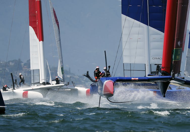
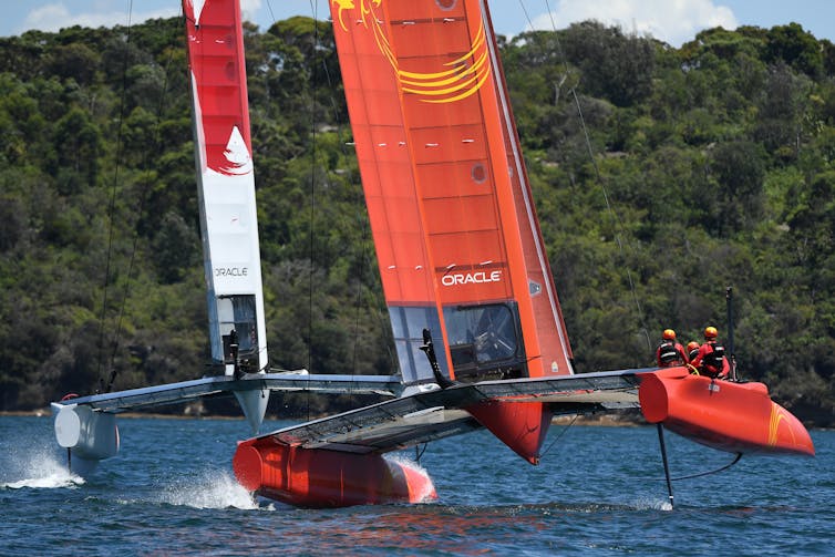
Sailing used to be considered as a rather sedate pastime. But in the past few years, the world of yacht racing has been revolutionised by the arrival of hydrofoil-supported catamarans, known as “foilers”. These vessels, more akin to high-performance aircraft than yachts, combine the laws of aerodynamics and hydrodynamics to create vessels capable of speeds of up to 50 knots, which is far faster than the wind propelling them.
An F50 catamaran preparing for the Sail GP series recently even broke this barrier, reaching an incredible speed of 50.22 knots (57.8mph) purely powered by the wind. This was achieved in a wind of just 19.3 knots (22.2mph). F50s are 15-metre-long, 8.8-metre-wide hydrofoil catamarans propelled by rigid sails and capable of such astounding speeds that Sail GP has been called the “ Formula One of sailing ”. How are these yachts able to go so fast? The answer lies in some simple fluid dynamics.
As a vessel’s hull moves through the water, there are two primary physical mechanisms that create drag and slow the vessel down. To build a faster boat you have to find ways to overcome the drag force.
The first mechanism is friction. As the water flows past the hull, a microscopic layer of water is effectively attached to the hull and is pulled along with the yacht. A second layer of water then attaches to the first layer, and the sliding or shearing between them creates friction.
On the outside of this is a third layer, which slides over the inner layers creating more friction, and so on. Together, these layers are known as the boundary layer – and it’s the shearing of the boundary layer’s molecules against each other that creates frictional drag.
A yacht also makes waves as it pushes the water around and under the hull from the bow (front) to the stern (back) of the boat. The waves form two distinctive patterns around the yacht (one at each end), known as Kelvin Wave patterns.
These waves, which move at the same speed as the yacht, are very energetic. This creates drag on the boat known as the wave-making drag, which is responsible for around 90% of the total drag. As the yacht accelerates to faster speeds (close to the “hull speed”, explained later), these waves get higher and longer.
These two effects combine to produce a phenomenon known as “ hull speed ”, which is the fastest the boat can travel – and in conventional single-hull yachts it is very slow. A single-hull yacht of the same size as the F50 has a hull speed of around 12 mph.
However, it’s possible to reduce both the frictional and wave-making drag and overcome this hull-speed limit by building a yacht with hydrofoils . Hydrofoils are small, underwater wings. These act in the same way as an aircraft wing, creating a lift force which acts against gravity, lifting our yacht upwards so that the hull is clear of the water.
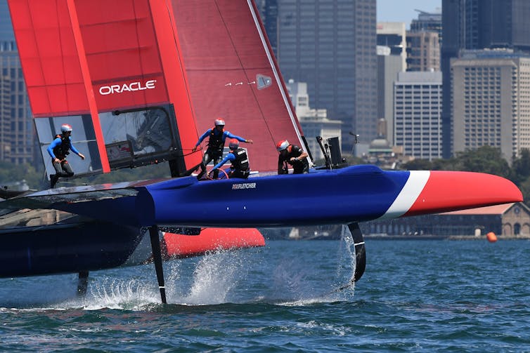
While an aircraft’s wings are very large, the high density of water compared to air means that we only need very small hydrofoils to produce a lot of the important lift force. A hydrofoil just the size of three A3 sheets of paper, when moving at just 10 mph, can produce enough lift to pick up a large person.
This significantly reduces the surface area and the volume of the boat that is underwater, which cuts the frictional drag and the wave-making drag, respectively. The combined effect is a reduction in the overall drag to a fraction of its original amount, so that the yacht is capable of sailing much faster than it could without hydrofoils.
The other innovation that helps boost the speed of racing yachts is the use of rigid sails . The power available from traditional sails to drive the boat forward is relatively small, limited by the fact that the sail’s forces have to act in equilibrium with a range of other forces, and that fabric sails do not make an ideal shape for creating power. Rigid sails, which are very similar in design to an aircraft wing, form a much more efficient shape than traditional sails, effectively giving the yacht a larger engine and more power.
As the yacht accelerates from the driving force of these sails, it experiences what is known as “ apparent wind ”. Imagine a completely calm day, with no wind. As you walk, you experience a breeze in your face at the same speed that you are walking. If there was a wind blowing too, you would feel a mixture of the real (or “true” wind) and the breeze you have generated.
The two together form the apparent wind, which can be faster than the true wind. If there is enough true wind combined with this apparent wind, then significant force and power can be generated from the sail to propel the yacht, so it can easily sail faster than the wind speed itself.
The combined effect of reducing the drag and increasing the driving power results in a yacht that is far faster than those of even a few years ago. But all of this would not be possible without one further advance: materials. In order to be able to “fly”, the yacht must have a low mass, and the hydrofoil itself must be very strong. To achieve the required mass, strength and rigidity using traditional boat-building materials such as wood or aluminium would be very difficult.
This is where modern advanced composite materials such as carbon fibre come in. Production techniques optimising weight, rigidity and strength allow the production of structures that are strong and light enough to produce incredible yachts like the F50.
The engineers who design these high-performance boats (known as naval architects ) are always looking to use new materials and science to get an optimum design. In theory, the F50 should be able to go even faster.
- Engineering
- Aerodynamics
Member, Human Research Ethics Committee
Student Recruitment Officer
Executive Editor
General Manager | La Trobe University, Sydney Campus
Lecturer / Senior Lecturer - Business Law & Taxation
Hull Design
We started by working with one of the sport’s most decorated and accomplished racing shell designers, Klaus Filter . Over the past 50 years, Filter-designed boats have won more international gold medals than any other hull and Klaus continues to refine his designs as our Chief Designer.
Our designers and engineering team use the latest CAD software to design and analyse the hull and cockpit to optimise performance, ergonomics and aesthetic design. This same process is applied to the design and construction of the small parts and fittings too.
RACING HULL SHAPES
Designed for : Elite Racing

The FLX is the culmination of years of painstaking research, analysis and improvement, designed to match heightened athlete fitness and technique parameters. Independent testing against other leading elite level brands proves unmatched performance – vital seconds which are the difference between winning and losing.
Designed for: Efficiency

Klaus Filter was the only slender hull designer to empirically test and account for human impact on rowing shells. He calculated and applied extensive data to refine the shape, waterline, and thus the wetted surface accordingly. What you get is a pragmatic hull that’s optimised for thru-water performance when rowed.
RECREATIONAL HULL SHAPE
Broader beam, shallower hull curve, these shells provide a greater level of stability than their pure racing brethren, but still offer manoeuvrability and sleekness not typically found in this class of recreational boat.

- Meet the ITMA Team
- Class Rules
- Class By-Laws
- 12mR Database
- Measurement Certificates
- The 12mR Class by Luigi Lang & Dyer Jones- Volume 1
- The 12mR Class by Luigi Lang & Dyer Jones- Volume 2
- 2024 PORQUEROLLES
- 2023 NEWPORT
- 2021 HELSINKI
- 2019 NEWPORT
- 2014 BARCELONA
- 2011 FLENSBURG
- WORLD CHAMPIONS
- 2017-2019 Series
- 2021 Regattas
- 2020 Regattas
- 2019 Regattas
- 2018 Regattas
- 2017 Regattas
- 2016 Regattas
- 2015 Regattas
- 2014 Regattas
- 2013 Regattas
- 2012 Regattas
- 2011 Regattas
- AMERICAS FLEET
- NORTHERN EUROPE FLEET
- SOUTHERN EUROPE FLEET
- Americas Fleet
- N. Europe Fleet
- S. Europe Fleet
- Coupe de France Series
- 12mRs for Sale
- 12mRs for Charter
- 12mR Brand Guide
- 12mR Team Store
Columbia, US-16

Built in 1958 according to the International Third Rule.
1958-1962: Built for the 17th America’s Cup campaign at a cost of $300,000, her design was a development of Vim. She was slightly longer on the waterline with reduced sail area, but this was compensated by the efficiency of newer sails (later Dacron) and the reduced thickness (resistance) of her keel. Briggs Cunnigham skippered her to victory at the Defender Trials over Weatherly , Easterner and Vim and ultimately to a 4-0 win over Sceptre for the America’s Cup. In 1960 she was sold to Paul Shields, who altered her keel, she participated in the Defender Trials for the 1962 America’s Cup.
1964-1975: Columbia was purchased by Thomas Patrick Dougan of Southampton, NY and Newport Beach. In 1966 her hull was altered, and although she performed well, she was dominated by Intrepid in the Defender Trials that year. In 1967 she won the Caritas Cup (NYYC) and the Lipton Memorial Trophy. In 1975 she was purchased by the Swedish Syndicate as a trial horse to Sverige .
1976-2000: Columbia was purchased by Pelle Petterson who modified her and sold her on to Xavier Rougert-Luchaire who used her as the trial horse to Lionheart in 1979. Her homeport was Cannes, France until 2000 when she was brought “home” to Newport by Paul Gardener and Bill Collins.
Owned by Alain Hanover
Purchased by Kevin Hegarty, 12mR Yacht Charters and was rebuilt at New England Boat Works (Portsmouth,RI) with a new keel designed by David Pedrick.
2019: Columbia (US-16) won the Traditional Division of the 2019 12mR World Championship at Newport, RI
Jump to Twelve Metre Yacht Club, Newport Station Fleet page for Columbia (US-16)


Fluid Dynamics: Performance Optimization in Yacht Design
Materials for yacht designers: hull design, furniture selection for yacht designers: interior design insights, lighting design in yacht designers: a guide to interior illumination, leasing options for yacht procurement: nautical financing in yacht designers domain, form stability in yacht designers: hull design, deck layout and design in yacht designers: the secrets of exterior excellence, textile choices in yacht designers interior design: the essentials.
Hull Design: Insights for Yacht Designers

Hull design plays a critical role in the performance and efficiency of yachts, making it an essential consideration for yacht designers. The shape and form of the hull directly impact characteristics such as speed, stability, maneuverability, and fuel consumption. For instance, let’s consider a hypothetical case study involving two similar-sized yachts with different hull designs. Yacht A has a deep V-shaped hull while Yacht B features a flat-bottomed hull. These distinct designs result in contrasting performances: Yacht A exhibits excellent seakeeping abilities, allowing it to cut through waves smoothly at high speeds; on the other hand, Yacht B offers enhanced stability when stationary or traveling at low speeds due to its wider base.
To gain valuable insights into yacht design, this article aims to delve into various aspects related to hull design. Firstly, we will explore the fundamental principles that underpin efficient hull shapes and their effects on hydrodynamics. This discussion will encompass concepts such as drag reduction techniques, optimization of water flow around the hull, and considerations for different operating conditions. Secondly, by analyzing case studies and real-world examples from renowned yacht manufacturers and naval architects, we will examine successful strategies employed in achieving optimal balance between performance, comfort, and safety through effective hull design strategies employed in achieving optimal balance between performance, comfort, and safety through effective hull design. We will highlight the importance of factors such as weight distribution, Hull materials , and structural integrity in ensuring a yacht’s overall performance and longevity.
Furthermore, this article will delve into the role of computer-aided design (CAD) software and advanced simulation techniques in modern yacht design. These tools enable designers to create and analyze various hull designs virtually, allowing for rapid iteration and optimization before physical prototyping. We will explore how these technologies have revolutionized the yacht design process, leading to more efficient and innovative hull designs.
Additionally, we will discuss the impact of environmental considerations on hull design. With increasing concerns about sustainability and fuel efficiency, yacht designers are exploring alternative propulsion systems and hybrid power solutions. The article will examine how these advancements influence hull design by requiring modifications to accommodate new components or optimize energy consumption.
Lastly, we will touch upon the future trends in yacht hull design. As technology continues to advance rapidly, concepts like hydrofoils and air lubrication systems are gaining traction in the industry. These innovations aim to further enhance speed, reduce drag, and improve fuel efficiency. We will provide insights into these emerging trends and their potential implications for future yacht designs.
Overall, this article aims to provide readers with a comprehensive understanding of the importance of hull design in yachts. By exploring various aspects such as hydrodynamics, CAD tools, environmental considerations, and future trends, readers can gain valuable insights into this critical aspect of yacht design.
Understanding the Importance of Material Selection
The choice of materials in Hull Design is a critical factor that significantly impacts the performance and durability of yachts. To illustrate this point, let us consider an example where two identical yachts are constructed using different materials – fiberglass and aluminum alloy. Both yachts undergo similar sailing conditions over a period of five years. At the end of this duration, it becomes evident that the yacht made from aluminum alloy exhibits signs of corrosion, while the one built with fiberglass remains robust and unaffected by such issues.
Material selection plays a crucial role in determining not only the structural integrity but also other important aspects such as weight distribution, buoyancy, and maintenance requirements. It is imperative for yacht designers to carefully evaluate various factors before making their material choices. One significant consideration is the intended use of the yacht – whether it will be predominantly used for racing or cruising purposes. Racing yachts often require lightweight yet strong materials like carbon fiber composites to maximize speed potential, whereas cruising vessels may prioritize comfort and endurance over sheer speed.
To evoke an emotional response in our audience, we can highlight key benefits associated with material selection through a bullet-point list:
- Enhanced Performance: The right choice of materials can optimize fuel efficiency and maneuverability.
- Cost-Effectiveness: Selecting durable materials reduces long-term maintenance expenses.
- Environmental Sustainability: Eco-friendly options minimize ecological impact during construction and operation.
- Aesthetics: Materials like teak wood contribute to visually appealing designs that enhance overall enjoyment.
Furthermore, evaluating different material properties using tables helps designers make informed decisions based on specific requirements. For instance, comparing strength-to-weight ratios, thermal conductivity levels, and resistance to corrosion allows for comprehensive analysis when choosing between alternatives.
In conclusion, understanding the importance of material selection is paramount in achieving optimal performance and longevity in yacht design. By considering factors such as usage requirements and appropriate comparisons between materials’ properties, designers can ensure they create vessels that offer both functionality and aesthetic appeal. In the subsequent section, we will delve into another critical aspect of hull design – achieving optimal stability in form.
Achieving Optimal Stability in Form
Section H2: Achieving Optimal Stability in Form
Transitioning seamlessly from the previous section’s discussion on material selection, it becomes evident that achieving optimal stability in form is crucial for yacht designers. This aspect of hull design ensures not only safe and comfortable navigation but also enhances overall performance. To illustrate this concept, let us consider a hypothetical case study involving two yachts with different stability characteristics.
Imagine Yacht A, constructed using lightweight materials such as carbon fiber composites, epitomizing modern engineering techniques. On the other hand, Yacht B embodies traditional construction methods utilizing heavier yet durable materials like wood or steel. Both yachts are designed to sail through rough seas and challenging weather conditions.
To achieve optimal stability in form, yacht designers must pay attention to various factors:
- Hull Shape: The shape of the hull greatly influences stability. Vessels with deep-V hulls tend to have better seakeeping abilities and enhanced maneuverability compared to flat-bottomed hulls.
- Center of Gravity (CoG): Properly positioning the CoG is vital for maintaining balance and preventing excessive rolling motions that can compromise stability.
- Ballast Systems: Incorporating ballast systems allows for adjustability depending on sea conditions by altering the vessel’s center of gravity.
- Metacentric Height (GM): GM determines a yacht’s initial stability against capsizing forces; therefore, designers need to strike an optimal balance between high initial stability and comfort at sea.
By considering these aspects during the design process, yacht builders can ensure their vessels possess superior stability attributes while navigating varying water environments.
Table: Factors Influencing Stability in Yacht Design
Achieving optimal stability in form is an ongoing process that demands meticulous attention from designers. By considering the aforementioned factors during the design phase, yachts can be constructed with enhanced stability attributes that promote smooth navigation experiences.
Transitioning smoothly into our subsequent section on “Balancing Weight for Enhanced Maneuverability,” we delve deeper into how Weight Distribution influences a yacht’s maneuvering capabilities without compromising its overall stability.
Balancing Weight for Enhanced Maneuverability
In the previous section, we explored the importance of achieving optimal stability in yacht design. Now, we will delve deeper into the techniques and considerations that yacht designers employ to achieve this crucial aspect of hull design.
To illustrate these concepts, let us consider a hypothetical case study involving a luxury sailing yacht designed for long-distance cruising. The designer’s primary goal is to ensure that the vessel maintains stability even under challenging sea conditions. By carefully analyzing various factors, such as weight distribution and shape, they can create a hull form that meets these requirements.
When it comes to optimizing stability in form, there are several key considerations that designers must keep in mind:
- Center of Gravity: Placing the center of gravity low within the hull helps to enhance overall stability by reducing the likelihood of capsizing or rolling excessively.
- Beam-to-Length Ratio: A wider beam relative to length provides increased initial stability, minimizing the risk of heeling over when subjected to strong winds or rough seas.
- Freeboard Height: Determining an appropriate freeboard height ensures sufficient reserve buoyancy and prevents excessive water ingress during heavy weather conditions.
- Hull Shape: Employing a deep-V or modified-V hull shape enhances directional stability and reduces resistance caused by waves, resulting in smoother handling characteristics.
These considerations are best illustrated through visual aids such as bullet points and tables:
- Reduced risk of capsize
- Improved resistance against rolling
- Increased comfort on board
- Safer navigation experience
By meticulously considering these aspects throughout the design process, yacht designers can strike a delicate balance between stability and performance – ensuring both safety and comfort for the vessel’s occupants.
In the upcoming section, we will explore “The Science Behind Efficient Water Flow” and how it contributes to optimizing a yacht’s performance. Understanding these hydrodynamic principles is crucial in achieving both speed and efficiency on the water, further enhancing the overall design of a yacht.
The Science Behind Efficient Water Flow
Building upon the importance of weight balance, another crucial aspect in yacht design is maximizing stability through hull geometry. By carefully considering the shape and form of the hull, designers can enhance a vessel’s stability characteristics, enabling it to navigate various water conditions with ease.
Example: Let us consider a hypothetical scenario where a yacht designer aims to create a stable vessel for ocean crossings. In this case, they would need to focus on specific aspects of hull geometry that contribute to stability, such as beam width and freeboard height.
Paragraph 1: One significant factor that influences stability is the beam width, which refers to the maximum width of the boat at its widest part. A wider beam provides increased lateral resistance against rolling motions induced by waves or winds. This enhanced stability offers passengers comfort during rough sea conditions and prevents excessive tipping or heeling. However, it is important to strike a balance between beam width and hydrodynamic efficiency since an overly wide beam may increase drag and reduce overall performance.
Paragraph 2: Another consideration in achieving optimal stability is determining the appropriate freeboard height – the vertical distance from the waterline to the deck level. Higher freeboards offer greater buoyancy reserve and minimize the risk of inundation during heavy seas or adverse weather conditions. On the other hand, lower freeboards provide reduced windage and improved handling but compromise safety in extreme situations. Striking an equilibrium between these factors ensures both adequate safety margins and efficient maneuverability.
- Increased stability enhances passenger comfort during challenging sea conditions.
- Optimal beam width strikes a balance between stability and hydrodynamic performance.
- Appropriate freeboard height guarantees safety while allowing for efficient handling.
- Finding an equilibrium between stability-enhancing features creates a well-rounded vessel capable of tackling diverse marine environments.
Paragraph 3 (Table): To further illustrate different elements affecting hull geometry and their impact on stability, the following table provides an overview:
Understanding how hull geometry influences stability is crucial in yacht design. However, it is equally important to ensure structural strength and durability for long-lasting performance.
Ensuring Structural Strength and Durability
Section H2: Ensuring Structural Strength and Durability
By ensuring that a yacht’s structure can withstand various environmental conditions and stresses, designers can guarantee its longevity and safety on the open seas.
To illustrate this point, let us consider a hypothetical scenario where a yacht encounters rough weather conditions during a transatlantic voyage. In such circumstances, the hull must be able to withstand powerful waves crashing against it without compromising its integrity. A well-designed hull would distribute these external forces evenly throughout its structure, reducing the risk of any damage or failure.
To achieve this level of structural robustness, there are several key factors that need to be considered by yacht designers:
- Material Selection: Optimal materials should be chosen for different parts of the hull based on their specific properties, such as tensile strength, corrosion resistance, and weight-to-strength ratio.
- Reinforcement Techniques: The strategic placement of reinforcements within the hull design can significantly enhance its overall strength and rigidity.
- Load Distribution: Yacht designers must carefully analyze anticipated load patterns on different sections of the vessel to ensure proper distribution and prevent localized stress concentrations.
- Quality Control Measures: Implementing stringent quality control processes during manufacturing is crucial to detect potential defects or weaknesses early on and rectify them before they compromise the vessel’s performance.
By incorporating these considerations into their designs, yacht designers can create structurally sound vessels capable of enduring even the most challenging maritime environments. Moreover, adhering to established industry standards and regulations further guarantees that yachts meet rigorous safety requirements.
Transitioning smoothly into our next section about enhancing performance through innovative design techniques, we will explore how novel approaches have revolutionized yacht construction and propelled advancements in speed, efficiency, and maneuverability at sea.
Enhancing Performance through Innovative Design
Transitioning from the previous section on ensuring structural strength and durability, we now turn our attention to another crucial aspect of yacht design: enhancing performance through innovative design. To illustrate this concept, let us consider a hypothetical scenario involving a yacht designer tasked with creating a high-performance racing sailboat.
In order to enhance performance, there are several key considerations that yacht designers must take into account:
Hydrodynamics: The hull shape plays a vital role in minimizing drag and maximizing speed. By carefully analyzing fluid dynamics and employing advanced computational methods, designers can optimize the hull form for superior hydrodynamic efficiency.
Stability: It is essential to ensure that the vessel remains stable even under extreme weather conditions or during sharp maneuvers. Incorporating features such as ballast systems and anti-heeling mechanisms helps maintain stability and improves overall safety.
Weight Reduction: Every extra kilogram adds resistance and slows down the boat’s acceleration. Designers aim to reduce weight wherever possible by using lightweight materials without compromising structural integrity.
Rigging Systems: Efficient rigging setups contribute significantly to overall performance. Innovative designs utilizing carbon fiber masts, adjustable sails, and optimized control systems allow for greater maneuverability and increased speeds.
To further illustrate these concepts, consider the following table showcasing different design elements employed in two hypothetical racing yachts – Boat A and Boat B:
As one can see from this example, Innovative design choices can greatly impact a yacht’s performance characteristics. By incorporating cutting-edge technologies and considering these key factors, designers have an opportunity to create vessels that excel in speed, stability, and maneuverability.
Transitioning into the subsequent section on key considerations for material choices, it is crucial to explore how different materials can further enhance yacht performance. By selecting appropriate materials based on their specific attributes and properties, designers can optimize both structural integrity and overall functionality of the vessel.
Key Considerations for Material Choices
In the pursuit of creating high-performance yachts, innovative design plays a crucial role. By pushing boundaries and exploring new concepts, yacht designers can unlock exceptional performance capabilities. This section delves into some key aspects that contribute to enhancing performance through innovative hull design.
To illustrate the impact of innovative design on performance, consider the case study of the renowned sailing yacht “Oceanic Dream.” Designed by an experienced team of naval architects and engineers, this yacht showcased groundbreaking features that revolutionized its performance in various conditions. One notable innovation was the implementation of a hydrofoil system, allowing Oceanic Dream to lift out of the water partially when reaching high speeds. This not only reduced drag but also improved stability and control, resulting in impressive speed gains during races.
When it comes to designing for enhanced performance, several factors come into play. These include:
- Hydrodynamics : Optimal water flow around the hull is essential for achieving higher speeds and maneuverability. Innovations such as streamlined hull shapes, underwater appendages like bulbs or wings, and advanced computational fluid dynamics simulations aid in reducing resistance and improving overall efficiency.
- Weight optimization : Minimizing weight while maintaining structural integrity leads to increased speed and better handling characteristics. The use of lightweight materials like carbon fiber composites or aluminum alloys allows for greater strength-to-weight ratios without compromising safety.
- Sail plan optimization : Efficient sail plans with modern rigging systems maximize propulsion from wind power alone. Advances in technology have enabled designers to create sails with lower weights, reduced aerodynamic drag, and adjustable shapes to adapt to changing wind conditions.
- Structural stiffness : A rigid structure ensures efficient energy transfer throughout the boat’s hull and reduces flexing under load. Incorporating advanced construction techniques and materials that provide optimal stiffness enhances responsiveness and improves overall performance.
In summary, innovative design in yacht hulls has the potential to dramatically enhance performance. Through advancements in hydrodynamics, weight optimization, sail plans, and structural stiffness, designers can create vessels that achieve exceptional speeds while maintaining stability and control. With these considerations in mind, we now turn our attention to another critical aspect of yacht design: maintaining form stability in challenging conditions.
“Building upon the foundations of enhanced performance through innovative design, it is imperative for yacht designers to also prioritize maintaining form stability in challenging conditions.”
Maintaining Form Stability in Challenging Conditions
Insights for Yacht Designers: Maintaining Form Stability in Challenging Conditions
In the world of yacht design, maintaining form stability is paramount to ensure a safe and comfortable sailing experience, particularly when faced with challenging conditions. One such condition that often tests a yacht’s stability is rough seas caused by high winds and large waves. To address this concern effectively, designers must consider various factors and implement strategic measures.
Firstly, hull shape plays a pivotal role in maintaining form stability during turbulent sea states. A narrow-beam vessel with deep V-shaped hull provides better resistance against rolling motion compared to wider or flatter-bottomed designs. This can be observed through an example where two yachts encounter harsh weather conditions at sea – one with a narrow V-shaped hull and another with a flat-bottomed design. The former demonstrates enhanced stability due to its ability to cut through the waves while minimizing roll angles.
Additionally, incorporating features like bilge keels or ballast systems can significantly augment form stability. Bilge keels are lateral extensions on each side of the hull that increase hydrodynamic lift while reducing rolling motion. On the other hand, ballast systems involve placing heavy materials low within the hull structure to lower the center of gravity and improve overall stability. These strategies work synergistically with appropriate hull shapes to enhance the yacht’s performance even when confronted with adverse environmental conditions.
- Hull shape: Narrow beam and deep V-shaped hulls offer increased resistance against rolling motion.
- Bilge keels: Lateral extensions added to reduce roll angles by increasing hydrodynamic lift.
- Ballast systems: Placement of heavy materials low within the hull structure lowers the center of gravity for improved stability.
- Windage reduction: Minimizing exposed surface area above deck reduces wind forces acting on the yacht.
Furthermore, it is essential for designers to evaluate their choices by analyzing various factors, such as the yacht’s intended use and anticipated sailing conditions. This evaluation process should involve considering real-world scenarios and conducting numerical simulations to validate design choices. By employing a systematic approach and integrating these insights into their designs, yacht designers can ensure that form stability is maintained even in challenging conditions.
Transitioning seamlessly into the subsequent section on “Optimizing Weight Distribution for Speed and Control,” it is vital for designers to recognize that weight distribution within a yacht significantly affects its performance. Achieving an optimal balance between different components, including fuel tanks, equipment placement, and accommodations, allows for improved speed, maneuverability, and overall control of the vessel. With this understanding in mind, let us explore the strategies employed to optimize weight distribution in yacht design.
Optimizing Weight Distribution for Speed and Control
Building upon the principles of maintaining form stability in challenging conditions, a successful yacht design also necessitates an optimized weight distribution for enhanced speed and control. By carefully considering the placement of various components and materials within the hull, designers can achieve superior performance characteristics that elevate the overall sailing experience.
To illustrate this concept, let us consider a hypothetical case study involving two identical yachts with different weight distributions. Yacht A is designed with most of its heavy equipment concentrated towards the bow, while Yacht B evenly distributes its weight throughout the hull. When both yachts encounter rough seas, Yacht A struggles to maintain stability due to excessive pitching and yawing caused by the forward-weighted configuration. Conversely, Yacht B exhibits better handling capabilities as its balanced weight distribution allows for improved maneuverability even under adverse conditions.
Optimizing weight distribution involves careful consideration of several factors:
- Center of Gravity (CoG): Efficiently positioning the CoG ensures optimal balance between fore-and-aft trim and port-starboard roll stability.
- Load Distribution: Distributing loads uniformly across various compartments reduces stress concentrations on specific parts of the hull structure.
- Ballast Placement: Strategic placement of ballast enables fine-tuning of stability and helps counteract heeling forces during sailing.
- Material Selection: Choosing lightweight but durable materials for non-structural components minimizes unnecessary added weight without compromising functionality or safety.
These considerations are best visualized through a table highlighting their impact when designing a yacht’s weight distribution:
By diligently addressing these factors, yacht designers can create vessels that not only excel in terms of speed and control but also enhance the overall sailing experience for their owners.
Mastering the art of hydrodynamic efficiency is another crucial aspect to be explored in the upcoming section. Understanding how a yacht interacts with water plays a pivotal role in further refining its performance capabilities.
Mastering the Art of Hydrodynamic Efficiency
Building upon the foundation of optimizing weight distribution, yacht designers must also master the art of hydrodynamic efficiency. By understanding how water interacts with a vessel’s hull, designers can create designs that minimize drag and maximize performance on the open seas.
Hydrodynamic Efficiency in Yacht Design:
To illustrate the importance of hydrodynamic efficiency, let us consider a hypothetical case study involving two identical yachts competing in a race. The first yacht has a streamlined hull design specifically engineered to reduce resistance as it slices through the water. In contrast, the second yacht features a less refined design with protrusions and irregularities along its hull surface. As these yachts sail side by side, it becomes evident that the first yacht experiences significantly less drag due to its optimized shape, granting it an undeniable advantage over its competitor.
Key factors influencing hydrodynamic efficiency include:
- Hull Shape: Streamlined hull shapes are essential for reducing wave-making resistance and minimizing frictional drag.
- Surface Smoothness: A smooth surface reduces skin friction drag caused by turbulence between the hull and surrounding water.
- Appendages Optimization: Properly designed appendages such as keels and rudders help maintain stability while minimizing unnecessary drag.
- Bulbous Bows or Sterns: These bulb-shaped extensions at either end of the vessel help improve speed by reducing bow wave formation or stern eddies.
It is worth noting that incorporating these elements into overall hull design requires careful consideration and trade-offs based on specific sailing conditions and intended use. By skillfully balancing these factors, yacht designers can achieve optimal hydrodynamic efficiency tailored to their clients’ needs.
As we delve deeper into enhancing yacht performance, it becomes evident that hydrodynamic efficiency is not the only crucial aspect. The next section will explore how structural integrity serves as a cornerstone in yacht design, ensuring safety and longevity on the open waters.
Structural Integrity: A Cornerstone of Yacht Design
Section H2: Mastering the Art of Hydrodynamic Efficiency
Building upon our understanding of hydrodynamic efficiency, we now delve into another crucial aspect of yacht design – ensuring structural integrity. By creating a robust and reliable structure, yacht designers can guarantee safety on the open seas while optimizing performance. In this section, we explore how structural integrity serves as a cornerstone in achieving excellence in yacht design.
To illustrate the significance of structural integrity, let us consider the hypothetical case study of a 60-foot sailing yacht designed to withstand harsh weather conditions encountered during ocean crossings. The hull is subjected to tremendous forces from wind, waves, and impacts with debris. By prioritizing structural integrity, designers must carefully select materials that offer both strength and resilience.
To achieve this goal effectively, several key considerations come into play:
Material Selection:
- Utilize high-strength composites or aluminum alloys known for their durability.
- Optimize material thickness based on stress analysis calculations.
- Incorporate advanced bonding techniques to ensure strong joints and connections.
Structural Reinforcements:
- Implement strategically placed carbon fiber reinforcements in areas prone to higher loads.
- Integrate bulkheads and frames to distribute stresses evenly throughout the hull.
- Employ appropriate reinforcement techniques such as laminating or infusion processes.
Safety Features:
- Install watertight compartments to prevent flooding in case of accidental breaches.
- Include emergency escape routes and deployable life rafts for crew members’ safety.
- Consider redundancy systems for critical components like steering mechanisms.
Rigidity Optimization:
- Minimize weight without compromising strength through careful engineering designs.
- Utilize computer-aided simulations to optimize rigidity-to-weight ratio.
Table: Benefits of Structural Integrity
By prioritizing structural integrity, yacht designers can create vessels that not only excel in terms of performance but also ensure safety on long voyages across challenging waters. Achieving excellence in structural design is essential to unleash the full potential of a yacht’s performance.
Moving forward, we will explore how optimizing sail plan and Hull Shape can further enhance a yacht’s overall performance without compromising its structural integrity.
Unleashing the Full Potential of Performance
Section H2: Advanced Hydrodynamics for Optimal Hull Design
Transitioning from the previous section on structural integrity, it is crucial to emphasize that achieving optimal performance in yacht design requires a deep understanding of advanced hydrodynamics. By harnessing the power of fluid dynamics, designers can unlock new possibilities and maximize the efficiency of a vessel’s hull.
To illustrate this point, let us consider a hypothetical scenario where two yachts with identical dimensions are racing against each other. The only difference between them lies in their respective hull designs. Yacht A features a traditional displacement hull, while Yacht B incorporates an innovative planing hull with stepped chines. As they navigate through choppy waters, it becomes evident that Yacht B gains a significant advantage due to its superior stability and reduced drag. This case study serves as a testament to the importance of incorporating cutting-edge hydrodynamic principles into yacht design.
When aiming for unparalleled performance in yacht design, several key factors must be considered:
Shape Optimization: Fine-tuning the shape of the hull is critical to minimize resistance and achieve higher speeds. Incorporating sleek curves and streamlined profiles reduces drag by effectively diverting water flow around the vessel.
Weight Distribution: Proper weight distribution helps maintain balance and stability during navigation. Strategically placing heavy components such as engines or fuel tanks lowers the center of gravity, improving overall handling and maneuverability.
Viscous Flow Analysis: Analyzing how water interacts with different parts of the hull enables designers to identify areas prone to turbulent flow or separation. By reducing these phenomena through careful modification, unnecessary energy loss can be minimized.
Material Selection: Choosing lightweight yet robust materials enhances both performance and durability. Utilizing composites or carbon fiber allows for greater strength-to-weight ratios without compromising structural integrity.
To further illustrate these concepts visually, we present you with a table showcasing four exemplary yacht designs along with their corresponding speed records:
By examining this table, it is evident that hull design plays a crucial role in achieving higher speeds. The planing and catamaran designs showcased the potential for faster navigation due to reduced drag and improved stability.
In summary, advanced hydrodynamics offer yacht designers an opportunity to push boundaries and unlock unparalleled performance. By optimizing hull shape, distributing weight strategically, analyzing viscous flow patterns, and selecting appropriate materials, designers can create vessels with superior speed and efficiency. Incorporating these principles into yacht design not only ensures enhanced functionality but also provides an exhilarating experience for owners and enthusiasts alike.
Related posts:
- Hydrodynamics and Yacht Designers: Hull Design
Performance: The Intricacies of Yacht Designers Hull Design
Previous weight distribution and hull design: insights for yacht designers, next nautical financing for yacht designers: a comprehensive guide, victoria j. manzo, related posts.

Weight Distribution and Hull Design: Insights for Yacht Designers
Suggested posts.

Color Schemes: Yacht Designers Interior Design Insights

Materials and Construction: The Key Elements in Yacht Design

Performance Optimization: Yacht Designers and Beyond
More stories.

Windows and Ports: A Guide for Yacht Designers: Exterior Design
SCOW HULLS – PART 1 – THE PROS
by ttisson | Nov 25, 2019 | Hull Design | 0 comments

The Yachting World hall of fame: 50 yachts that changed the way we sail
- Helen Fretter
- May 13, 2020
We asked historians, round the world race winners and legendary sailors to name the yachts that changed the sport for good. In no particular order, these are the 50 yachts that shifted how we sail...

Photo: Guido Cantini / Panerai / Sea&See.com
1. Mariquita
Built: 1911 Design: William Fife III
Mariquita is a living link between the ‘Big Class’ behemoths, such as Britannia , the J Class and all that went after, including the hugely popular 12-metres. The 125ft gaff cutter was launched as part of a new 19-metre class designed to pitch matched yachts against one another.
Just four were built. Mariquita performed well, particularly in light airs. She also, uniquely, survived. Having been used as a houseboat for many years, she was discovered in the mud in 1991 and lovingly restored to relaunch in 2003, and she still races today.

Photo: Oskar Kihlborg / Volvo Ocean Race
2. ABN Amro One
Built: 2005 Design: Juan Kouyoumdjian
Two Volvo Ocean Race -winning skippers nominated Juan Kouyoumdjian’s ABN Amro One , the 5.6m beam, aggressively chined winner of the 2005-06 race. Her skipper Mike Sanderson comments: “I am biased, but I think ABN Amro One was very special and really did change people’s thinking about what made a good offshore race boat.
“As this was the first generation of Volvo 70s it was always going to be an interesting time seeing how people translated the rule,” says Sanderson. The other factor was many of the team’s involvement in Open 60 sailing.
“We very much looked at the concept of the boat differently: no spinnaker pole, furling No.4 Jibs, twin rudders, lazyjacks, snuffers on spinnakers… They all went from being equipment that was only used on single-handed boats to our team thinking it could make us faster around the world, day in day out.”
Article continues below…

Yours for €2.75 million – Mariquita, the elegant and glamorous 125ft Fife design
Not very often does a yacht come on the market that has such a storied history behind her. Marquita, the…
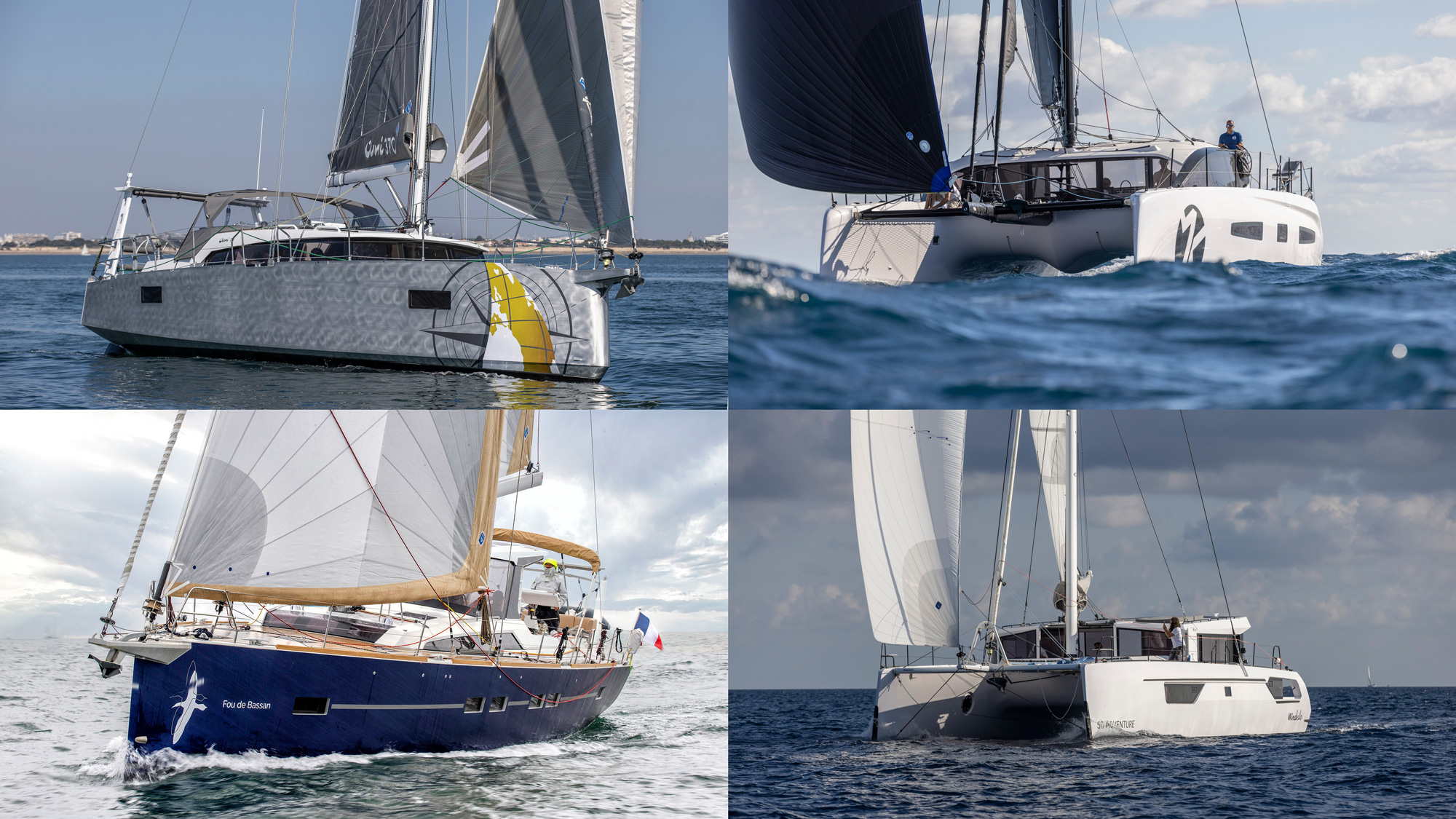
43 of the best bluewater sailboat designs of all time
Which yacht is the best for bluewater boating? This question generates even more debate among sailors than questions about what’s…
Ian Walker , winner of the 2014-15 Volvo Ocean Race, recalls: “This generation of boats smashed the previous 24-hour records and made the 600-mile day possible. ABN Amro was quite radical structurally but the key thing was she prioritised stability over anything else – such as wetted surface area.
“The Farr boats were lower wetted surface area and even started out with spinnaker poles! Asymmetric spinnakers meant sailing higher angles and more often needing righting moment.
“ABN Amro One also had twin rudders and more transom immersion, which meant it was slow in light winds but fast at high speed. There was some doubt when it was last in the first in-port races and because much of the race is in light winds, but it was so fast reaching that it negated any weaknesses.”
The black boat went on to win six of the nine offshore legs. Sanderson adds: “In all the Volvo 70s that where built – and to be honest in all the offshore boats that have followed ( Rambler , Comanche etc.) – you can see a bit of ‘Black Betty’ as we nicknamed her.”

Photo: Thierry Martinez
3. TP52 Patches
Built: 2007 Design: Reichel Pugh
Originally created to produce fast yachts for the Transpac Race, the TP52 class developed into an owner-driven inshore circuit which continues to attract the world’s best monohull sailors (these days as the Super Series). One development refined on the TP was the change to wide aft sections.
“We started off with quite narrow sterns and the working deck stopping well over one metre forward of the stern,” comments class manager Rob Weiland. “We now see an almost continuous width of the working deck from Beam Max aft and the working deck continuing to the stern.
“The ‘powerful stern’ is now the norm in offshore racing. I’m not sure whether we started it, but for sure, we were the test bed for how to refine that hull shape concept for windward leeward performance.”
First to have a working deck all the way aft was the 2007 Reichel Pugh Patches , a style then taken a stage further by ETNZ (2009), which added slab-sided topsides with a knuckle to create more hull stability when heeled. ETNZ also saw refinements in deck layout, elements of which have filtered down to more mainstream designs, such as transverse jib car tracks.

Photo: Ivor Wilkins Offshore Challenges / DPPI
4. B&Q Castorama
Built: 2004 Design: Nigel Irens
‘Mobi’, as she was affectionately known, was the 75ft trimaran designed by Nigel Irens specifically for Ellen MacArthur’s solo round the world record attempt in 2004.
B&Q Castorama was highly optimised, being longer, narrower, and with more freeboard than the ORMA 60s, reducing the risk of a pitchpole.
She was also, uniquely, custom built for a petite female skipper, with a full-scale mock up of the cockpit created at Offshore Challenges office. The trimaran took over a day off Francis Joyon’s record to finish in 71 days and 14 hours.

5. J/24 Ragtime
Built: 1976 Design: Rod Johnstone
It took 18 months for Rod Johnstone to build this 24-footer in his garage in Connecticut. It was designed to be simple to sail, with few rig adjustments, and light enough to be trailable. Rod’s family helped sand and finish the boat, and she was called Ragtime . Competing at their local race series in the summer of ’76, Ragtime was so successful that many people asked Rod for a sistership. He quit his job, and with brother Bob Johnstone set up J-Boats.
Their confidence proved well placed. Just two years later the J/24 class had its own one-design fleet at Key West in 1978, with 20 boats on the line. Now over 5,500 boats have been built and sold worldwide.
The J-boat line expanded to include one-designs like the J/70, as well as cruiser-racers such as the J/109. It has since has become synonymous with asymmetric sailing, doing much to popularise the use of asymmetric spinnakers on big boats.
- 1. Introduction

Composite Applications
Carbon composite materials in modern yacht building.
A catamaran built almost entirely from lightweight, high strength carbon fibres is set to circumnavigate the globe using solar power alone. Jürgen Klimke, Sales Director Europe, and Daniel Rothmann, Manager Technical Sales, SGL Technologies GmbH, discuss the PlanetSolar project.

Many spectacular attempts have been made to circumnavigate the globe. Whether by land, sea or air, as soon as the technical opportunities were created, projects sprang up to realise this dream in the most unique way possible. Given the international fame and recognition that attend the achievement of such an ambitious goal, there will probably always be new projects that will fill observers with amazement.
But a project that is certainly unique in the history of such adventures is the circumnavigation of the globe with a catamaran made from carbon fibre reinforced plastic (CFRP) and equipped with the latest photovoltaic technology. Powered entirely by solar energy, the TÛRANOR PlanetSolar is due to set off on its voyage around the world early in 2011.
Raphael Domjan from Switzerland and Gérard d’Aboville from France will be on board the Tûranor PlanetSolar to navigate the 31 m long, 15 m wide craft across the world’s oceans. The adventurer d’Aboville was the first man to row across the Atlantic in 1980, and later, the Pacific.
Minimising weight
The catamaran is fitted with more than 500 m 2 of solar modules. The photovoltaic cells mounted on the deck and on flaps at the stern and sides give the craft its characteristic appearance. But one of the biggest challenges has been to store enough solar energy so that the vessel can maintain its progress even in darkness. To achieve this, use has been made of the latest lithium-ion batteries, which weigh around 11 tonnes in total. The batteries are housed in the left and right floats – the two hulls that run the full length of the boat.
To minimise consumption of precious energy as the craft cruises along, it was necessary to save as much weight as possible in the boat structures by employing modern lightweight construction technology. Through the use of carbon fibre composite in the hull structure, the requirements for excellent mechanical properties combined with very low weight were successfully met.
The four electric motors are driven by a massive power supply and provide a maximum output of 120 kW. The catamaran is moved and steered by two large propellers, which are also produced from carbon fibre materials and fitted on the end of each float. The propellers can be independently controlled to steer the craft on the desired course. The maximum speed is approximately 14 knots.
PlanetSolar‘s virtually silent and pollution-free circumnavigation of the globe is scheduled to take about 160 days. Several stops along the equator are planned to give a wider international audience the opportunity to learn more about this unique project.
The giant catamaran is currently being finished in the Knierim Yachtbau shipyard at Kiel in northern Germany, and initial tests have already been successfully completed following the christening and launch of the vessel on 31 March 2010. But before it can set off on its voyage around the world in early 2011, a considerable amount of detailed work and trials have still to be carried out to guarantee the success of the project.
Composite construction
Knierim Yachtbau is an established company that specialises in building individual high-tech yachts. It has already made a name for itself in a wide variety of projects as one of the leading manufacturers of innovative yachts constructed with composite materials. For example, Knierim Yachtbau successfully implemented projects such as the ‘UCA,‘ one of the largest German ocean racing yachts, and the ‘Container‘ in 2008. The first German America’s cup yacht, ‘Germany 1,‘ also came from the Kiel shipyard. Knierim Yachtbau recently introduced a new 10 m long, thoroughbred racing yacht with a fast, ultra-modern hull shape, which is set to create quite a stir. Here again, it used the favourable properties of carbon fibre composites in the construction of the hull, as did the mast maker for the mast.
The Kiel shipyard has over 40 years’ boat building experience and has developed great expertise in the use of composites, and carbon fibre materials in particular. So it is not surprising that, in planning the TÛRANOR PlanetSolar, it was decided to use carbon fibre again.
The catamaran had to be lightweight and yet at the same time extremely stable in construction to meet the exacting demands of the open sea. After several proposals, ranging from a single-hull boat to a trimaran, the company finally opted for a double-hull design by Craig Loomes, director of the LOMOcean company in New Zealand. The design of the TÛRANOR PlanetSolar catamaran is based on the so-called ‘wave piercer’ principle. This means that the two catamaran hulls are designed to slice through the waves in rough seas, so helping the craft adopt a stable, solid position in the water.
The high stresses expected in foul weather conditions during the voyage made it necessary to use high strength carbon fibre for the hulls. Steffen Müller, one of the two managing directors of Knierim Yachtbau, points out that the stresses under storm conditions should not be underestimated, since in very high seas, the central hull will also thrust through the waves.
In the production of the hull in Kiel, most of the work was carried out using the hand lay-up process with vacuum compression, which made it possible to ensure an optimum fibre volume content. The moulds for the hull were produced by Knierim Yachtbau itself, which has its own CNC 5-axis milling machine to make the master patterns and the moulds.
The Knierim shipyard‘s Tooling division also designs and produces moulds for the wind power industry, e.g. for rotor blades, and for automotive components. The moulds for the TÛRANOR PlanetSolar are based on a steel bottom frame and a Styropor block, which was machined to the correct contours using the CNC milling machine. Coated with high quality epoxy pastes the moulds were then shaped to the final contours by repeated finishing to give them a high quality surface. Owing to the immense size of the yacht, the moulds for the hull structure and the deck were each divided into three different sections and then assembled in the production hall to give the complete mould.
Altogether, more than 20 tonnes of carbon fibres, 11 tonnes of foam core and 20 tonnes of epoxy resin and hardener were used in the construction of this boat.
Carbon fibre
Carbon fibre materials were supplied by the SGL Group , headquartered in Wiesbaden, Germany. In the construction of the TÛRANOR PlanetSolar, the Knierim shipyard used three different carbon fibre materials from SGL: a unidirectional fabric; a bidirectional fabric with weights of 300-400 g/m 2 ; and a SIGRATEX® woven carbon fabric with similar weights.
In the construction of multilayer fabrics such as bidirectional fabrics, the different layers are applied with the required alignment to one other (e.g. ±45°) and then stitched together fully automatically with polyester thread. This method produces very good cohesion of the individual fibre rovings and allows the fabric to be more easily placed and aligned in the hull mould.
Another advantage of these fabrics is that, unlike in woven fabrics, the fibres are always straight and non-crimped. As a result, the intrinsically very high strength and stiffness values of the carbon fibres are retained and mechanical tensile and compression forces can be optimally absorbed by the composite structure.
In addition to unidirectional and bidirectional fabrics, special structures with three or four layers can be tailored to meet particular load-bearing requirements.
By using these multilayer fabrics, it is possible to reduce the work involved with placing the material in the mould. Instead, only one complete fabric consisting of different individual layers with different fabric weights needs to be placed. This represents a saving in production time and costs for the user. In hand lay-up with vacuum compression or vacuum infusion, these fabric designs allow good impregnation of the individual rovings and so result in high component quality.
In the production of these fabrics, SGL uses mainly the SIGRAFIL® C carbon fibres manufactured in its plants in Scotland and the USA. At present, two different types are produced at SGL, a 50K heavy tow carbon fibre and a 24K carbon fibre. The standard feedstock used for these fibres is polyacrylonitrile (PAN), which is based on a highly polymeric organic substance with a high carbon content. Through the successive processing steps of oxidation and carbonisation carried out at carefully controlled temperatures, the basis of the subsequent carbon fibres is created. These processing steps are followed by surface treatment to apply different sizings such as polyurethane or epoxy. In the case of the TÛRANOR PlantSolar project, the carbon fibres used were those with an epoxy sizing.
Before the different woven and multiaxial fabrics were used in the TÛRANOR PlanetSolar yacht, they first had to be certified to the special marine requirements of Germanischer Lloyd (GL), together with the SGL SIGRAFIL C carbon fibre.
Unique project
The TÛRANOR PlanetSolar yacht is an excellent example of the opportunities opened up by using modern carbon fibre materials. Built with high-performance materials and equipped with the latest technology, the carbon catamaran fulfills all the requirements of a unique and prestigious project. As in other industries where eco-friendly drive concepts are required for the future, this yacht represents a milestone in international yacht building thanks to its lightweight construction and photovoltaic technology.
It will take an estimated 68 000 man hours before the 85 tonne craft is completely finished. The great moment will come in spring 2011, when the yacht will set off on its voyage around the world. The plan is to start in the Mediterranean and then circumnavigate the globe in a westerly direction. Points of call on this adventure will include cities such as New York, San Francisco, Singapore and Dubai. We look forward to following the progress of this adventure and hope for a successful and safe voyage around the world.
This feature was published in the July/August 2010 issue of Reinforced Plastics magazine.
Further reading

Case study: The Farr 400

Hodgdon employs core thermoforming in yacht build

SP specifies composite materials for Rogers yacht

Carbon fibre producers optimistic in downturn

Hungarian company builds racing yacht

PlanetSolar to sail around the world in 2011
Hull Smoothness – What Matters for Speed?

How much effort should you spend on hull smoothness? We decided to investigate this after seeing a variety of approaches. Many (maybe most) fast sailors put time into polishing the hull, but others don’t bother.
Our primary source for this article is A Smooth Bottom is a Fast Bottom from the GP14 class website. This article is an easy read and the best summary we found. Author Paul Grimes was a Collegiate All-American sailor at Brown University and has experience in hydrodynamics and marine yacht services. We also referred to Sailing Theory and Practice , by C.A. Marchaj
Hull Smoothness and Speed – Data
Hull drag results from several factors. These factors have different names, depending on which book you read.
- Skin friction drag – the friction from the hull sliding through the water. A smooth hull reduces skin friction.
- Form drag – related to the streamlining of the hull and foils.
- Wave-making resistance – related to the slowing effect of the waves produced at the bow and stern by the boat’s movement.
- Induced resistance – due to leeway as the boat slides to leeward while sailing upwind.
Skin friction causes a substantial portion of total drag. Marchaj’s data from towing tests shows that skin friction for an International Canoe is 80% of total drag at 3 knots. Skin friction increases with boat speed, but other the forms of hull drag increase more, so skin friction is only 40% of total drag at 6 knots.
What is the speed advantage of a smooth hull? We could not find definitive speed data. Marchaj’s data only compares a boat with a clean bottom to a boat with a foul bottom. With the same driving force, the clean-bottom boat travels 0.27 knots faster than the foul-bottom boat when moving at 4 knots. The difference shrinks to 0.14 knots when the boats are moving at 6 knots. These are significant differences.
Since we couldn’t definitive data beyond foul and clean hulls, we’ll have to review the concepts of laminar and turbulent flow to get more answers about hull smoothness.
Laminar and Turbulent Flow
The no-slip condition and the boundary layer.
It may be counterintuitive, but the water molecules immediately next to the moving hull are pressed against the hull and adhere to it – they don’t slip. This is true regardless of the hull’s smoothness. These molecules slow down the water molecules “above” them, and so on until the water further from the hull is no longer affected. The affected layer is called the boundary layer. Skin friction drag is determined by the type of flow within the boundary layer.
The type of flow in the boundary layer determines the amount of skin drag.
- In laminar flow, the water molecules in the boundary layer all flow in the same direction – parallel to the hull surface.
- In turbulent flow, the water molecules move more chaotically.
Benefits and Limitations of Laminar Flow
Laminar flow reduces skin friction by as much as 80%, compared to turbulent flow. However laminar flow is fragile. It turns into turbulent flow under several conditions.
- Surface is not fair (bumps or dents).
- Surface is not extremely smooth (highly polished), especially in the forward part of the hull.
- Water is flowing fast. At speeds greater than 4 knots or so, boats can’t sustain laminar flow over the hull length, regardless of smoothness.
- Distance traveled along the surface is long. As the distance traveled becomes long, it becomes impossible to sustain laminar flow, no matter how smooth the hull.
Turbulent Flow
Although turbulent flow causes more drag, there’s still a very thin laminar layer in turbulent flow. The skin drag is minimized if the surface roughness is less than this thin laminar layer.
Conclusions about Hull Smoothness
The theory leads to the following conclusions about how much you should do about hull smoothness.
Fair the Hull
To be competitive your hull should be fair. Small undulations over a distance are not significant. Dents and bumps, especially those with sharp edges are more significant, as they will trip the flow from laminar to turbulent.
Polish to 400 Grit for Acceptable Results
Even with a highly polished hull, boats moving faster than several knots will transition to turbulent flow within the first several feet of hull. In turbulent flow, more roughness is acceptable. Grimes says that sanding to 400 grit is adequate if the flow is turbulent.
Polish to 1200-1500 Grit Equivalent for Best Results
The best chance for sustaining laminar flow is with a very smooth (e.g., 1200-1500 grit or greater) hull traveling at low speeds (light air). Pay special attention to the forward part of the hull, since roughness there will trip the flow to turbulent sooner.
For light air and overall peace of mind, polishing to 1200-1500 grit is not outlandish, but only if you have time to do the more important stuff – like practicing.
Other Hull Drag Factors
Waxing and water beading.
Beading of water on the hull has no effect on skin friction drag. The no-slip condition still holds true. If you put wax on just to get beading, you may make the surface rougher. We’ll see more about this in a future article.
Foil Smoothness
The foils (boards and rudder), being narrower, can sustain laminar flow over their entire surface. Foil smoothness is thus more important. We’ll cover this in a separate article.
Do You Have the Right Touch? Thoughts from Bruce Goldsmith
Hull care – how to get smooth and stay that way, you may also like, prevent breakdowns – top tips, updated, dehumidifying your a-scow, mc boards sticking three potential causes, season prep tech tip: clean your pulleys, stabilize the rig for mooring or on-water..., hull care – how to get smooth..., maintenance tips and myths for cleaning and..., leave a comment cancel reply.
You must be logged in to post a comment.
This site uses Akismet to reduce spam. Learn how your comment data is processed .
Insert/edit link
Enter the destination URL
Or link to existing content
Types of Racing Sailboats

Last Updated by
Jacob Collier
August 30, 2022
Sailboats come in many different shapes and sizes depending on a variety of factors. This means there are a variety of sailboat racing boat types on the market.
When you look specifically at racing sailboats, you will notice several different aspects that separate them from other sailboats. You might be wondering, what are the types of racing sailboats?
There are many types of racing sailboats that range from one-man dinghies all the way to 100-foot yachts. Some racing sailboats are classified as keel boats, multi-hull, and even a tower ship. These boats are built primarily for speed, so comfort is usually an afterthought depending on the brand.
For racing sailboats, each one is going to fit within a specific race category. So depending on the type of race will dictate the types of sailboats you will see.
According to sailboat data, racing boats have slightly different designs that stand out compared to bluewater sailboats. Looking at the Olympics is another example of what other racing sailboats are out there.
Table of contents
Characteristics of Racing Sailboats
There are quite a few sailboats made today that are geared specifically towards racing. They have one purpose, which is to go as fast as possible.
Some racing sailboats are advanced far more than the average ones, which is completely up to the buyer. For example, America’s Cup race showcases “foiling boats” that run on foils under the hulls. These allow the sailboats to go faster than 50 MPH.
If you are searching for boats that have characteristics to fit within a specific race type, you will find that many boats can enter different races depending on the rules. The most popular sailboat races are:
- Offshore/Oceanic
There are key features that separate racing boats from other sailboats and allow them to enter specific races. These can be narrowed down to the hull design, the type of keel, how many masts it has, and what type of sails are used.
Size of Racing Sailboats
As mentioned, these boats range from smaller dinghies to 100-foot yachts. Depending on the type of race will determine the type of boat that is being used.
The size of certain boats might prevent them from entering races where only smaller ones are allowed. There are exceptions in some races, like a handicapped fleet race, that will adjust the rating to allow their final time to be adjusted. The reason some races are handicapped to a certain extent is so a captain and his crew can determine the outcome and not a boat that is at an advantage.
Overall Design
With racing sailboats, they are subject to racing against the wind about half of the time. The angles of the boats are still similar to cruisers but greatly differ in the size of the sails to allow the sheets to have a better shape.
As racing boats are typically trying to sheet the sails hard, they are trying to keep them within the centerline. This allows the sails to be flatter and change them as needed.
Over time, the sails will typically wear out faster than the ones being used on regular sailboats. Since they are aggressively being used to stretch in the wind, they are subject to more use than regular sailboats.
Similar Looking Sailboats
There are races that only accept sailboats called one-design. These sailboats are built to exact specifications and are nearly identical to one another.
The reason that these boats are designed is to help combat any potential advantages from one boat to the next. It does not really set itself apart from other boats, but it is a good start to get into racing.
Lack of Interior Accommodations
Racing sailboats typically lack anything special on the inside to help save weight and go faster. Since a lot of features are not available, this means it would be nearly impossible to liveaboard full time.
In most scenarios, a true racing sailboat strictly has one purpose: to go fast. This does not mean that all racing sailboats cannot have luxury or comfort, since boat racing has been in existence since boats were first invented for water.
You would need to find boats that have a great balance between using them on weekends and racing. There are plenty of options to consider for what you want to accomplish in racing and comfort.
Types of Sails Being Used
Another characteristic that separates racing boats from cruisers is the types of sails that are being used. Both are designed for performance but are measured a bit differently. Racing sails are meant for speed, as regular sails are meant for cruising.
Depending on the goal of sailing, such as racing, you could look into purchasing sails that are specific to racing. Would you rather take off an extra minute or two of your time with a long upwind leg during a race or have the same durable sail for another five years out?
This opens up the door to endless possibilities of sail-making materials to get the job done. Most cruisers use Dacron or laminates that use a high-stretch fiber. With racing boats, light laminate sails have proven to be more durable and last longer than previous racing sails.
Popular Types of Racing Sailboats
Since the goal is to be around 50 MPH and have the best handling, many options have to be considered for the type of boat to possess both. Since comfort is not a deciding factor, it is somewhat easier to narrow down a racing boat over a bluewater or cruiser boat.
The types of racing sailboats that cater to you will all depend on your budget and your main goal of use. Each series of boats has its main purpose, with some having a little bit of comfort with racing.
Yachts and Super-Sized Sailboats
Yachts that specialize in racing tend to have a solid mix between speed and comfort. With a fiberglass hull and roughly 50 feet or so in length, these boats are not easily handled by just one or two people like others or there.
With that being said, they are also the most expensive out of the group. Even with exceptionally older models, you are still easily looking at $100,000.
You can expect to see racing yacht sailboats to reach about 17 MPH. Depending on the size, they can go faster or slower.
High-Performance Cruisers
Some boats can do it all when it comes to all-around performance . If you are looking for a boat that you can race for fun but still want to take it out offshore and live on, then you need to look at high-performance cruisers that can do both.
These boats generally range between 25 to 40 feet and are similar to yachts. However, they do not have as much luxury in comparison but the price tag is not nearly as heavy.
Trailerable Sailboats
Trailerable sailboats fall into similar categories like the dinghy and small racing boats. These boats can range in length up to 27 feet but are limited in their height and weight.
These serve a purpose for just about anything to do with sailing, but the racing ones are strictly for racing. Their design is meant for speed, not the comfort of heavy-duty performance offshore.
Small Racing Sailboats
Smaller racing sailboats are built to be lighter and have practically nothing on board compared to cruisers or dinghies. Due to their smaller size, they often get mistaken for larger dinghies even though they typically range between 20 and 70 feet.
These smaller racing sailboats are related to cruising sailboats but are a bit smaller. They are cousins to sailing dinghy boats that are used for racing. They also have fin keels and utilize laminate sails.
Sailing Dinghies
Dinghies are a category of small boats that have a wide variety of uses. If you are new to boating, it is a great place to start learning due to its size and simplicity.
These typically only need one or two people at most and are no longer than 15 feet in length at max. Many of these boats are competitively raced and will also result in a wet ride no matter what you do. You will see these types of boats used in certain Olympic events.
Racing Cruising Sailboats
Cruisers have a wide range in size and length, as they range between 16 and 50 feet or more. They feature cabins for extended cruising and have standing headroom below deck if over 26 feet.
Popular brands on the market have introduced models that are fit for racing. These are great for fleet races or for boats that are associated with cruising. With that being said, it is a great compromise for boaters that enjoy racing but also want to cruise whenever they want.
The cutter features a single mast and mainsail, which is very similar to common sailboats like a sloop. A cutter sailboat has the mast further aft which allows the attachment of the jib and staysail.
In high winds, a smaller staysail can still be flown from the inner stay. This used to be a traditional racing design back in the day.
Cutters are great for both offshore and coastal cruising. In addition, they can still be utilized as a racing boat depending on the conditions.
Fractional Rig Sloop
Fractional rig sloop sailboats were popular in the 60s and 70s, but have steadily made a comeback in today's market. This sloop’s forestay will not cross at the highest point of the mast, meaning it attaches at a lower position.
On fairly windy days when you do not have to utilize full power, the fractional rig allows the crew to slightly bend the tops of the mast and flatten out sails. This greatly affects performance and is a great option for cruising, one-design races, and even handicap sailing.
Schooner Sailboats
These particular sailboats have multiple sails which are protected by two masts. These are known as the mainmast and foremast, with the foremast being close to the ship’s foredeck and a lot shorter than the mainmast.
Depending on the size of the schooner, additional masts can be added to allow more sails. These are great for offshore cruising and sailing but can be an effective racing boat.
Trimarans and Catamarans
Trimarans have three of their hulls side by side and “cats” only have two. In comparison, they both share very similar characteristics for racing and overall performance.
Trimarans are quicker and easier to build than catamarans, so, therefore, they are more common. They both have similar restrictions on space and can be used for day sailing.
In addition, they are not as stable as compared to other sailboats out there. There are still various ways to use them and they make for great racing boats since they can reach up to 10 MPH.
How Can These Boats Go Faster?
Each person will select a racing boat that fits their needs accordingly. If you enjoy racing, but continue to lose against boats that are the same, you might want to consider either your team, the technique behind it all, or the boat itself. Routine maintenance is going to be the best thing you can do when checking to see if your racing sailboat can go any faster.
The hull has to be in top shape and needs to be able to hold tension. The sails also need to be checked to make sure they are not overly stretched or worn out.
The masts also need to be of the right stiffness, as they are bending with tension from the rigging. This one might have to be professionally calibrated if you do not know how to do it, especially since every boat with its mast is going to measure differently based on size and shape.
Finally, the weight of the boat could be the determining factor in winning or losing. Make sure the weight is appropriate and the maximum amount for the boat is not exceeded.
Related Articles
Types of Sailboats: A Complete Guide
Born into a family of sailing enthusiasts, words like “ballast” and “jibing” were often a part of dinner conversations. These days Jacob sails a Hallberg-Rassy 44, having covered almost 6000 NM. While he’s made several voyages, his favorite one is the trip from California to Hawaii as it was his first fully independent voyage.
by this author
Best Sailboats
Most Recent

Affordable Sailboats You Can Build at Home
Daniel Wade
September 13, 2023

Best Small Sailboats With Standing Headroom
December 28, 2023
Important Legal Info
Lifeofsailing.com is a participant in the Amazon Services LLC Associates Program, an affiliate advertising program designed to provide a means for sites to earn advertising fees by advertising and linking to Amazon. This site also participates in other affiliate programs and is compensated for referring traffic and business to these companies.
Similar Posts

Best Bluewater Sailboats Under $50K

Best Blue Water Sailboats Under 40 Feet

Which Sailboats Have Lead Keels?
June 20, 2023
Popular Posts

Best Liveaboard Catamaran Sailboats

Can a Novice Sail Around the World?
Elizabeth O'Malley
June 15, 2022

4 Best Electric Outboard Motors

How Long Did It Take The Vikings To Sail To England?

10 Best Sailboat Brands (And Why)
December 20, 2023

7 Best Places To Liveaboard A Sailboat
Get the best sailing content.
Top Rated Posts
Lifeofsailing.com is a participant in the Amazon Services LLC Associates Program, an affiliate advertising program designed to provide a means for sites to earn advertising fees by advertising and linking to Amazon. This site also participates in other affiliate programs and is compensated for referring traffic and business to these companies. (866) 342-SAIL
© 2024 Life of Sailing Email: [email protected] Address: 11816 Inwood Rd #3024 Dallas, TX 75244 Disclaimer Privacy Policy
- OC Wally Cento
- 84 Mini Maxi
- IMOCA Open 60
- Consultancy Services
- 30m Blue Water Cruiser
- 25m Explorer Yacht
- 24m Fast Cruising Catamaran
- 23m Performance Cruiser
- 20m Explorer Yacht
- 20m High Performance Cruiser
- 18m Blue Water Cruiser
- 15m Performance Cruiser
- 15m Explorer Yacht
- 12m Explorer Yacht
- Multihull Design
- 18m Explorer Yacht
- 40m Blue Water Cruiser
- 40m Cruiser Racer
- 33m Performance Cruiser
- 30m Wally Cento
- 24m ORCsy Racer Cruiser
- 24m Day Sailer
- Carbon Component Design
- Yacht Performance Development
- CFD and Model Testing
- Twin Rudder Steering Systems
- Custom Deck Hardware
- Modifications and Refit
- VPP Routing and Sail Analysis
- Classic Yacht Refit & Optimisation
- Naval Architecture
- Engineering
- Rudder Design
- Brokerage Services
- 'Seahorse Magazine' #192
- Lucent #180
- Influence #171
- 'Eora' #169
- 'The Three Brothers' #168
- 'Edenred' #165
- Polka Dot #154
- 'Teata' #148
- ‘Sensei’ #131
- 'Sabre II' #93
- French Pineapple #79
- 'Letto Di Pletto' #47
- 'Mowgli' #41
- 23.8m Ultime Trimaran
- 20.7m Orma Trimaran
- 18.28m Orma Trimaran
- 16.75m Cruising Catamaran
- 16.1m Cruising Catamaran
- 12.8m Crowther Shockwave Catamaran
- 9.1m Seacart 30 Trimaran
- 26.3m Aluminium Sloop
- 22.38m Aluminium Classic Yacht
- 21.0m Steel Schooner
- 21.0m Aluminium Cruising Ketch
- 20.0m Aluminium Explorer Yacht
- 20.0m Luca Brenta Racer Cruiser
- 19.6m Aluminium Bluewater Cruiser
- 19.2m Aluminium Lifting Keel Sloop
- 18.23m Mylius Racer Cruiser
- 16.0m Sly Cruiser Racer
- 14.5m Aluminium Cruising yacht
- 13.87m Wooden Motor Sailer
- 11.6m Classic Pilot Cutter
- 25.25m Reichel Pugh Maxi
- 18.28m IMOCA 60 One Planet
- 18.28m O Canada IMOCA Open 60
- 18.28m Come in Vendee Open 60
- 18.23m Mylius FD Racer Cruiser
- 15.84m TP52 Racing Yacht
- 15.25m Pegasus Open 50
- 10.89m Figaro 3
- 10.1m Figaro 2
- 14.5m Aluminium Cruising Yacht
So, while the above static numbers are interesting, Figure 1 illustrates what the shape of center line of the three yachts looks like viewed from the side.
Hull #1 is red Hull #2 is blue Hull #3 is green
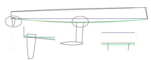
These lines show the rocker (the curve of the yacht longitudinally) on the centreline at 0 angle of heel. To make it clearer what’s happening at the middle and stern of the yacht there are two inserts at a higher scale.
Mid-ships around the keel one can see that the trade off in the green hull to having a narrower waterline beam is to have a deeper canoe body. Such that, for the same overall maximum draft the narrower yacht would appear to have a shorter, less efficient keel fin.
However, what we’re more interested in is the affect at the stern (which is highlighted in the sketch of page 3) where the angle of Hull #1 to the waterline is less than Hull #2 and Hull #3.
The two sets of sections illustrated in Figure 2 make it clearer the difference in the hull shapes drawn for the three yachts which result in the figures shown in the table of hydrostatic values. While in profile view it’s not all clear that there is any great difference in the hulls, in section view this is made much more apparent. One can see for instance that if it were not for the introduction of a ‘virtual vertical cutting place’ through Hull #1 that the beam of the yacht would be far greater than the other two hulls. This shows clearly another mis-conception that the chine is somehow an important hull device with magical properties. This is hardly the case; the chine is in fact a result of a decision to terminate the beam of what would be an otherwise very wide hull prematurely. It is the general characteristics of the hull form that are the most important aspect not the fact that there is a chine, although by scrutinising the line of the chine one can discern and make assumptions about some of those hull characteristics.
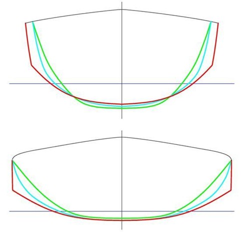
Figure 3 illustrates the three different sets of hull lines as they approach the transom. In simple terms one can imagine that as water flows along parallel to the hull that it exits in the direction of the three arrows and that the total drag force is represented by F1, F2 and F3. Note that these forces are not parallel with the waterline and so it follows that there must be a vertical component of force acting downward pulling the stern of the yacht down into the water. Since the angle of F3 is greater to the waterline than F1, the vertical force associated with F1 is greater than F3. In other words, for the same value of drag the stern of the narrower yacht is being forced down more than that of the wider yacht. This is only one area where static values (such as in the table) are over-shadowed by what happens once the yacht is in motion, particularly at speeds approaching and exceeding hull speed.
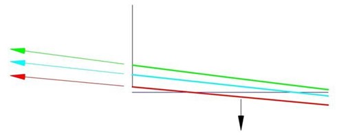
Figure 4 illustrates the effect of the couple created by F down at the stern and the corresponding F up at the bow. The two forces create what is known as a ‘couple’ about the center of mass/center of buoyancy of the yacht. The greater the value of F down the more sail force and longer it takes for the yacht to escape it’s own stern wave, rise over it’s bow wave and begin to operate in semi-planing mode where the yacht’s displacement is effectively reduced by the overall lift created by the pressure differences over the underwater body of the yacht . Once in semi-planing/semi-displacement mode as the yacht increases speed the values of F down and F up increase. Again, in simple terms, if the yacht is not correctly designed for high speed/Froude number planing what happens is that the bow rises prematurely and waterline length decreases.
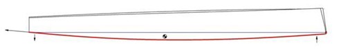
While the bow rising looks cool and is important at some point, particularly at very high speeds and in waves, it is not quick. It’s not rocket science to comprehend that a 77’ yacht displacing 28000kg is faster than a 70’ yacht displacing 28,000 kg.
OCD’s twin rudder moderate beam low rocker hulls are designed to allow a yacht of relatively light displacement to exit displacement mode earlier, begin semi and full planing earlier while maintaining maximum waterline length with minimum drag in the process. The trade off is higher drag at low speeds, but as you will recall this is mitigated to a great extent once the yacht begins to heel by careful hull design.
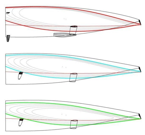
Figure 5 illustrates another factor with respect to heel, which of course a yacht spends a good deal of its time doing. Illustrated here are the three hulls at twenty four degrees of heel with the resultant static waterlines shown in their three respective colours. This is a slightly simplified situation since as we’ve described the stern is more greatly immersed underway than it is when theoretically static. However, this is a useful graphic since in the real world there are also waves passing down the hull. The centreline of the yacht in each case is in red and one can see clearly that for a yacht of this beam it would not be possible to have a single rudder at the stern. Hence the reason why single rudders are generally pushed further forward on the hull even though this reduced their effectiveness for a given area when turning or balancing the yacht.
What can be seen is how well immersed the smaller twin rudder is and also how it is also almost vertical in the water thereby creating side forces that are more or less parallel to the waterline. On the other hand there is a distinct angle to the single rudder blade and this is not so much important in terms of the loss of effectiveness of the rudder itself and increased drag with heel. More importantly and rarely understood is that as weather helm is applied to bare the yacht’s bow away, because of the angle of the single rudder to the waterline, a proportion of the rudder forces are driving the bow deeper in the water, increasing the forces causing the weather helm in the first place and so a self perpetual negative cycle is in train. This remains a little understood and considerable advantage both in terms of drag and safety/dynamic stability for twin rudder yachts.
Finally page 6, since yachts spend a good deal of their time heeled we don’t design them thinking of them sat at 0 degrees of heel and designers use so called buttock lines to look at what the hull looks like when heeled.
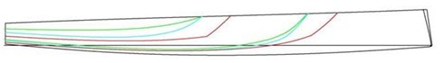
If one imagines a saw blade parallel to the centreline of the yacht and offset say 1.5m outboard. Then, pass the saw blade vertically down through the deck and hull of the yacht one will have cut the boat in two. When viewed from the side you would see a hole in the side of the yacht and the edge of the shape of this hole would be the buttock line at 1.5m.
This is what is illustrated by six coloured lines in Figure 6. In each case they show the 1.5m and 2.5m buttock lines for hulls #1, #2 and #3. The importance of these when were we to zoom in would be that one can see that the angles of the buttocks (effectively the heeled rocker lines) are equivalent to those that we see in Figure 3, in that the lines with the least rocker and so least dynamic drag are for Hull #1.
For more information on the OC 77 described in this article go to: OCD 77 High Performance Day Sailer
For more information regarding OC's design process go to: Naval Architecture
RETURN TO: Home page - Performance Yacht Design 101
RACE RESULTS
FARR MAGAZINE
GET UPDATES
ENVIRONMENT
DESIGNS BY LENGTH
DESIGNS BY NUMBER
VOLVO OCEAN RACE
SUPERYACHTS
AMERICA'S CUP
FEATURED DESIGNS
See all of our designs >
Design № 844 (43ft. | 2018)
FARR 43 CRUISER/RACER
Design № 841 (41ft. | 2018)
Design № 826 (60ft. | 2018)
IMOCA OPEN 60
LATEST NEWS
Read more news >
As the weather warms up all our thoughts turn to the 2018 racing season. It’s time to get the boat put back together and get those ratings certificates revalidated. IRC, ORCi and ORR have all undergone refinements that can have a significant impact on your handicap. Our team of designers follows the rule changes in detail and can quickly advise how these changes may impact you and what modifications may be worth considering for this season.
We offer a range of services to suit any budget. From a simple certificate review to identify potential sources of measurement error, to a complete performance versus handicap optimization program targeted to your specific race program and budget we are here to help.
Contact us at [email protected] or +1 410 267 0780 to find out how we can help make 2018 your best season yet.
BALTIC 142 Released from Mold
Published on June 30, 2018
The hull of Design 788 - Baltic Yachts Custom 142 has been released from the mold at the yard in Finland. Farr Yacht Design was responsible for the Naval Architecture on this project including specification of the innovative Dynamic Stability Systems foil that promises improved handling, reduced heel angles and improved speeds. This is the largest foil assisted sailing yacht to be developed and follows from extensive work and design studies to optimize the hull and foil package.
We are the top racing-yacht design team in the world based upon one of the most extensive, impressive records of winning yacht racing results ever compiled by a single design group. Our long-running record of achievement dates back more than 30 years and includes 43 world championships won in Farr designs and a multitude of design successes at internationally prestigious grand prix yachting events.
Learn about us & our services >
DESIGNED TO PERFORM
Farr Yacht Design
100 Severn Avenue, Suite 101
Annapolis, MD 21403
© 2018
More From Forbes
Rossinavi’s no limits brand sells first yacht two weeks after announcement.
- Share to Facebook
- Share to Twitter
- Share to Linkedin
Rendering of the No Limits NL45, the first of the fleet sold just two weeks after Rossinavi CEO ... [+] Federico Rossi presented the new brand to the world. The yacht sold to an American buyer.
Rossinavi CEO, Federico Rossi, held a global online presentation on Feb. 19 announcing the launch of a new brand of yachts in the Rossinavi lineup. No Limits was introduced to the world, delivered in a no-nonsense, minimalistic format perfectly suited to this crossover yacht brand synchronizing tech and function. Rossi emphasized that the philosophy of the No Limits brand would match the character of an explorer yacht with the style and charm of a superyacht.
Just two weeks after the No Limits brand launch, an American buyer stepped up and bought the first of the fleet, an NL 45 that is expected to launch at the end of 2025. The yacht will sport a 9.1-meter molded beam with an indoor gym connected to the outdoor beach club, four lower deck guest cabins, formal salon and dining space, full beam main deck owner's suite with a private office and dual baths, alfresco dining area and intimate sky lounge, outdoor foredeck lounge and pool area, and expansive 110 square meter sun deck.
The aluminum hull and superstructure of the NL45 has a GT just under 500, is solid, light, and 100 percent recyclable. The NL45 can accommodate 10 guests served by 5 crew. The 4,000 nautical mile range at 10 knots can rev up to a 15-knot top speed, with propulsion by two Cat 32 engines developing 1,193 bkW each.
No Limits offers five vessels from 30 meter, 37 meter, 37+ meter, 45 meter, and 45+ meter layouts. All models, Rossi noted in his launch presentation, would have a similar family feel, technical features, distribution of space, guest and crew areas, stability, comfort, and safety as protagonists of the No Limits fleet.
Large panoramic windows to allow natural light and great connections to the outdoors complement the multi-level cockpit and beach club. The 110 square meter sundeck on the 45 model is designed to accommodate a variety of uses, day or night. Pools, American bars, BBQ areas, sunbeds, and easy to raise windbreaks keep the space active and usable.
Lawyers Who Voided Elon Musk’s Tesla Pay Package Seek $6 Billion In Legal Fees
Wwe smackdown results, winners and grades as the rock returns, jamie dornan says ‘the tourist’ is a mad love story amid anarchy.
A sky lounge on the upper deck features a wrap-around view from large windows, making it attractive as a VIP cabin with a private outdoor deck.
The Rossinavi faciility at Vireggio where "Made in Italy" excellence is an essential part of doing ... [+] business.
The Philosophy
Rossi explained that the main aspect of the No Limits brand philosophy is PRO. He stated, in addition to representing the professional approach of the brand backed by 40 years of Rossinavi experience, that PRO represents Performance, Reliability, and Optimization.
The Mechanicals
Heavy duty engines and generators paired with two independent rudders for redundancy and maneuverability make the NL45 easy to manage. The double stabilization system with four fins is designed to improve comfort both at anchor and underway.
The Zero Noise system connecting shaft lines to thrust bearings rather than the gear box has mechanical advantages but also minimizes noise and vibration. Guests will appreciate the quiet comfort of the effective Zero Noise Rossinavi technology.
The tropicalization of the AC system has redundancy built into the machinery with chillers designed to operate at 150 percent capacity. Water management, dry and cold storage, and fuel capacity are all designed for spending extended time at sea. Unrestricted navigation for transatlantic crossings combined with Panama and Suez certification make No Limits yachts charter-ready global vessels prepared for adventure.
New look, new brand, new logo, in a clean, simple marque that matches the brand philosophy reflects ... [+] the mindset of the changing yacht client.
The New Look
In a simple logo that suggests the exterior bow design of the No Limits line, Rossinavi is taking a minimalistic, simple, forward-looking approach. The group encourages potential buyers to think in terms of endless routes in a dynamic and stylish yacht.
Exterior design by Fulvio de Simoni Studio in La Spezia, Italy and interiors by The Touch Studio of Amsterdam elevate the No Limits line in blending technology, comfort, and luxury into this high marine attitude yacht. That's a concept which should prove attractive to changing buyer profiles in the yachting industry.

- Editorial Standards
- Reprints & Permissions

French sailor Caudrelier wins first round-the-world multi-hull race
B attered but still skimming the waves, French sailor Charles Caudrelier crossed the line in Brest in the west of France on Tuesday to win the Ultim Challenge, the first solo round-the-world race for multi-hull boats.
Caudrelier, in the trimaran Gitana-Edmond de Rothschild, outdistanced the other survivors from the six-boat fleet as he covered more than 28,000 miles (51,000 km) in 50 days. He became just the eighth sailor to sail round the world in a multi-hull.
The boat, launched in 2017, was the first Ultim designed to 'fly' by rising out of the water on her foils as the boats swept down the Atlantic and then circled the globe passing south of the Cape of Good Hope, Cape Leeuwin in Australia and finally Cape Horn.
"I had the impression of becoming a machine, a robot connected to performance, a kind of killer who doesn't give up a nautical mile," Caudrelier told AFP during the race, saying he became "totally connected" to his boat.
The 'Ultim' multi-hulls are big and fast. Edmond de Rothschild is 32 metres (105 feet) long by 23 metres wide.
"To sail solo around the planet in a multi-hull at an average speed of 28 knots (51 km/h) is mind-boggling", said Olivier de Kersauson, who was the third man to complete a solo circumnavigation on a multihull in 1988.
The boats are also fragile.
Tom Laperche, in SVR Lazartigue, retired after duelling at the front with Caudrelier for 20 days.
The two sailors closest to Caudrelier both lost time when their boats suffered damage forcing them to make stopovers.
Thomas Coville, who was running second in Sodebo, the boat in which in 2016 he became one of four sailors to complete a solo non-stop circumnavigation in a multi-hull. Armel Le Cleac'h in Banque Populaire was lying third.
- Delayed arrival -
Eric Peron in Adagio and Anthony Marchand in Actual, the oldest Ultims in the fleet, quickly fell behind, but were still battling up the South Atlantic on Tuesday.
Only Caudrelier managed to complete the crossing without any major mishaps although he suffered a cut arm.
He nearly flipped his boat in the South Atlantic in what he described as "a moment of inattention".
"The boat went up on its edge, but the safety systems saved me and (the boat) fell flat again."
Caudrelier had enough of a lead to take that he was able to play safe and delay his arrival in Brest. With a storm threatening as he neared home, Caudrelier took shelter for three days in the Azores, before sailing for home on Monday, his 50th birthday, and arriving on Tuesday morning.
"It was special, strange, but I always felt like I was in the race," he said. "The weather has been on my mind a lot over the last few days.... I really wanted to find a hole to go home in."
Colville was amused.
"It's a funny race when the leader has the opportunity to go to a hotel while waiting for a good window to finish and, like a good sailor, leave at just the right time," he said.
fd/jld/pb/gj

IMAGES
COMMENTS
Source: INEOS. Each British vessel took around 46,000 hours to build, 90,000 hours to design, 75- to 100 thousand hours to CNC machine, and weighs around 6,450 tonnes. The yachts also include ...
J Class yacht Velsheda sailplan. LOA: 39.25m/128ft 9in · LWL: 27.8m/91ft 3in · Beam: 6.57m/21ft 7in · Disp: 180 tonnes. Original lines: Charles E Nicholson. Modified design: Dykstra Naval ...
He hull of a yacht is a complex three-dimensional shape, which cannot be defined by any simple mathematical expression. Gross features of the hull can be. ... Zero and negative sheer may be found on some extreme racing yachts and powerboats. The vertical distance between the sheer line and the waterline.
Multi-hull racing is another popular type of yacht racing and involves boats with two or more hulls. These boats are generally faster and more agile than monohulls, and races are often held over a short course. These races can be highly competitive, with teams of experienced sailors vying for position and race victory.
Sails provide power, foils the lift, which makes the hull the third critical leg of the AC75. Hull design has always been the most venerated aspect of an America's Cup yacht. The name on the ...
A single-hull yacht of the same size as the F50 has a hull speed of around 12 mph. ... The other innovation that helps boost the speed of racing yachts is the use of rigid sails. The power ...
We started by working with one of the sport's most decorated and accomplished racing shell designers, Klaus Filter. Over the past 50 years, Filter-designed boats have won more international gold medals than any other hull and Klaus continues to refine his designs as our Chief Designer. Our designers and engineering team use the latest CAD ...
In 1987 when we designed our first racing yacht, an 11m trimaran the hull and outrigger lines were drawn on computer at a time when the majority of yachts were still hand drawn. A velocity performance prediction (VPP) software program for multihulls didn't exist at that time and so designer Merfyn Owen created one, writing the software in ...
Yacht racing is a sailing sport involving sailing yachts and larger sailboats, as distinguished from dinghy racing, which involves open boats. ... displacement, and hull shape. During the 1920s and through the 1970s the Cruising Club of America established a formula by which most racing/cruising boats were designed during that period.
To this end, the team invested in three separate boats: a Decision 35 one-design catamaran for inshore racing, an MOD 70 trimaran and—most spectacularly of all—the 131-foot maxi-tri Spindrift 2. Originally launched as Banque Populaire V , the VPLP-designed behemoth is already the current Jules Verne Trophy holder, having circumnavigated in ...
The 115 year-old International 12 Metre Class encompasses a living history of racing yacht design by the world's foremost naval architects including Olin Stephens, Clinton Crane, William Fife III, Philip Rhodes, Johan Anker, Ben Lexcen and more who pushed their designs to the very limits of innovation. ... In 1966 her hull was altered, and ...
A racing yacht is a high-end vessel that is built for performance, generally costing far more than average racing vessels. ... Listed hull types include monohull, displacement, planing, catamaran and other. Built by a wide variety of yacht building companies, there are currently 765 racer yachts for sale on YachtWorld, with 171 new vessels for ...
Victoria J. Manzo July 4, 2023. Hull design plays a critical role in the performance and efficiency of yachts, making it an essential consideration for yacht designers. The shape and form of the hull directly impact characteristics such as speed, stability, maneuverability, and fuel consumption. For instance, let's consider a hypothetical ...
The hull and appendages are a development of successful Class 40 designs such as our #157, Cape Racing Yachts, seen above. Proven high performance, dynamically stable, both easily driven in the light as well as capable of being pushed hard in moderate breeze and in waves. On the offshore design, the forestay attaches well aft of the stem ...
PART ONE - THE PROS. Racing yacht design is regularly presented as a choice between power (in other words righting moment) and efficiency (primarily associated with drag). While correct, a more complete picture of a boat's performance is can be better explained by : hydrodynamic efficiency and righting moment on one side and aerodynamic ...
The optimisation procedure has been applied to a hull having l WL =6.65 m, designed with the traditional method (Larsson and Eliasson, 1996). The main characteristics of the yacht are listed in the third column of Table 1 (more details can be found in Mancuso, 2001). These parameters (from row 1 to row 7) refer to a sailing yacht designed to ...
Ian Walker, winner of the 2014-15 Volvo Ocean Race, recalls: "This generation of boats smashed the previous 24-hour records and made the 600-mile day possible.ABN Amro was quite radical ...
Knierim Yachtbau recently introduced a new 10 m long, thoroughbred racing yacht with a fast, ultra-modern hull shape, which is set to create quite a stir. Here again, it used the favourable properties of carbon fibre composites in the construction of the hull, as did the mast maker for the mast. The Kiel shipyard has over 40 years' boat ...
Deformability and buckling load of yacht hulls with fiber reinforced plastic sandwich structure depend on the stack sequence of the skins. In this work an optimization of fiber directions of the laminae for a racing yacht is proposed. This procedure has been divided into three parts (i.e. material characterization, surface model definition, lay ...
A smooth hull reduces skin friction. Form drag - related to the streamlining of the hull and foils. Wave-making resistance - related to the slowing effect of the waves produced at the bow and stern by the boat's movement. Induced resistance - due to leeway as the boat slides to leeward while sailing upwind.
There are many types of racing sailboats that range from one-man dinghies all the way to 100-foot yachts. Some racing sailboats are classified as keel boats, multi-hull, and even a tower ship. These boats are built primarily for speed, so comfort is usually an afterthought depending on the brand. For racing sailboats, each one is going to fit ...
Racing Yacht Sales. 25.25m Reichel Pugh Maxi; 22.38m Aluminium Classic Yacht; 20.0m Luca Brenta Racer Cruiser; 18.28m IMOCA 60 One Planet; 18.28m O Canada IMOCA Open 60; 18.28m Come in Vendee Open 60; 18.23m Mylius FD Racer Cruiser; 16.0m Sly Cruiser Racer; 15.84m TP52 Racing Yacht; 15.25m Pegasus Open 50; 10.1m Figaro 2; Explorer Yacht Sales ...
Contact us at [email protected] or +1 410 267 0780 to find out how we can help make 2018 your best season yet. The hull of Design 788 - Baltic Yachts Custom 142 has been released from the mold at the yard in Finland. Farr Yacht Design was responsible for the Naval Architecture on this project including specification of the innovative Dynamic ...
The yacht sold to an American buyer. Italian Sea Group. Rossinavi CEO, Federico Rossi, held a global online presentation on Feb. 19 announcing the launch of a new brand of yachts in the Rossinavi ...
Thomas Coville, who was running second in Sodebo, the boat in which in 2016 he became one of four sailors to complete a solo non-stop circumnavigation in a multi-hull. Armel Le Cleac'h in Banque ...
Mercury Racing's new low-emission, high-performance engine is designed for UIM Formula 4s class catamaran tunnel hull boats. Explore. Back. Explore View All. Overnight Cruising; House Boats ... The 60 APX is engineered to meet the unique needs of the UIM Formula 4s class catamaran tunnel hull boats, a category that showcases composite boats ...
This year's Boat Race will be the 169th time that Oxford and Cambridge's men have raced against each other and the 78th time the women's crews have done so. The course is the usual 4.2-mile ...
Against a backdrop of skyscrapers and super yachts, eight airborne athletes competed "Ironman"-style in the inaugural Jet Suit Race Series, an event organized by the Dubai Sports Council and ...
Michael Holt was aiming to row across the Atlantic Ocean to raise money for two charities. A 54-year-old man from north Wales has been found dead on his boat during an attempt to row across the ...
The home secretary has agreed to meet with the family of a student murdered in Hull. Libby Squire was raped and murdered by Pawel Relowicz in January 2019. It emerged Relowicz, who was jailed for ...