

Form Stability in Yacht Designers: Hull Design
Window treatments: enhancing yacht interiors with elegant designs.
- Fluid Dynamics: Performance Optimization in Yacht Design
Insurance Coverage for Yacht Design: Nautical Financing
Hull design: insights for yacht designers, rig design: performance optimization for yacht designers, textile choices in yacht designers interior design: the essentials, exterior finishing: a guide for yacht designers in exterior design, keel design in yacht designers: performance optimization.

Keel design plays a crucial role in optimizing the performance of yachts. The shape and characteristics of the keel greatly influence a yacht’s stability, maneuverability, speed, and overall sailing capabilities. Through careful analysis and experimentation, yacht designers strive to develop innovative keel designs that enhance performance and ensure competitive advantages for their vessels. In this article, we will explore the significance of keel design in yacht performance optimization, focusing on its impact on various aspects such as hydrodynamics, aerodynamics, and structural integrity.
To illustrate the importance of keel design in enhancing performance, let us consider a hypothetical scenario involving two identical yachts competing in a prestigious offshore race. Yacht A is equipped with a traditional deep-draft fin keel commonly found in older designs, while Yacht B features a modern bulb-keel configuration. As they navigate through challenging wind conditions and varying sea states during the race, it becomes evident that Yacht B exhibits superior upwind performance compared to Yacht A. This advantage can be attributed to several factors influenced by the keel design, including reduced drag from the bulbous lead appendage below and improved righting moment due to better weight distribution along the hull. Such differences exemplify how keels significantly affect a yacht’s ability to sail efficiently and effectively in different conditions.
One of the key aspects influenced by keel design is hydrodynamics. The shape and profile of the keel determine how water flows around it, affecting drag and lift forces. A well-designed keel minimizes drag by reducing turbulence and creating a smooth flow of water along its surfaces. By reducing drag, the yacht can maintain higher speeds while expending less energy, resulting in improved performance.
Additionally, the keel plays a crucial role in generating lift, which helps to counteract heeling forces caused by wind pressure on the sails. Lift is generated as water flows over the curved surfaces of the keel, creating a force that opposes heeling and contributes to stability. A properly designed keel will maximize lift while minimizing induced drag, allowing the yacht to maintain a balanced and controlled sailing attitude.
Aerodynamics also come into play when considering keel design. The shape and position of the keel influence airflow around the yacht’s hull and rigging. A streamlined keel reduces wind resistance, allowing for smoother sailing and increased speed. Moreover, by optimizing the interaction between the keel and other components such as the mast and sails, designers can minimize turbulence caused by air passing over these structures.
Structural integrity is another critical consideration in keel design. The weight distribution of the keel affects how forces are distributed throughout the yacht’s hull. A well-balanced distribution ensures optimal stability and prevents excessive stress on certain areas of the boat. Furthermore, modern materials and construction techniques enable designers to create lighter yet stronger keels that enhance performance without compromising safety.
In conclusion, keel design plays a significant role in optimizing yacht performance across various domains such as hydrodynamics, aerodynamics, and structural integrity. Through careful analysis, experimentation, and innovation, designers strive to develop efficient and effective keels that deliver superior stability, maneuverability, speed, and overall sailing capabilities. By understanding the significance of keel design in yacht performance, sailors and designers can make informed decisions to achieve competitive advantages in the world of sailing.
The Importance of Keel Design in Yacht Performance
When it comes to yacht design, a crucial element that significantly impacts performance is the keel. The keel plays a vital role in maintaining stability and maneuverability on the water, making it an essential consideration for yacht designers. To illustrate its significance, let’s consider a hypothetical scenario where two identical yachts participate in a race. However, one has an optimized keel design while the other has a suboptimal one.
Firstly, an optimally designed keel contributes to improved sailing performance by enhancing stability. A well-designed keel provides sufficient resistance against lateral forces caused by wind or waves, preventing excessive heeling or rolling motions. In our hypothetical race scenario, the yacht with the optimized keel maintains better balance and stability compared to its counterpart with the suboptimal design. This advantage allows it to maintain higher speeds and more efficient sail trim throughout the race.
Secondly, the choice of keel design directly affects maneuverability during different sailing conditions. For instance, a racing yacht may require quick course changes or tight turns when navigating around buoys or avoiding obstacles. An intelligently designed keel can provide enhanced agility and responsiveness in such situations, allowing the yacht to change direction swiftly without losing momentum. On the other hand, a poorly designed or inadequate keel may hinder these maneuvers, reducing overall performance and competitiveness.
To further emphasize the importance of proper keel design in yacht performance optimization, consider the following emotional bullet points:
- Increased speed: An optimized keel design enables faster sailing speeds due to reduced drag.
- Enhanced safety: Appropriate weight distribution through effective keel design improves overall stability and reduces risks of capsizing.
- Improved comfort: Well-balanced yachts equipped with optimal keels offer smoother rides even in challenging sea conditions.
- Competitive edge: Yachts with superior keels have an advantage over their rivals in races by achieving higher speeds and maneuverability.
Additionally, let’s include a table that compares the characteristics of different keel designs:
In conclusion, the importance of keel design cannot be overstated when it comes to optimizing yacht performance. The hypothetical scenario and emotional bullet points presented highlight the significant impact an optimized keel can have on speed, safety, comfort, and competitiveness. In the subsequent section about “Factors to Consider in Keel Design,” we will explore key considerations that yacht designers must take into account to achieve optimal performance.
Factors to Consider in Keel Design
The Importance of Keel Design in Yacht Performance has been established, and now we turn our attention to the various factors that need to be considered during the design process. To illustrate these considerations, let us delve into a hypothetical case study involving two yacht designers who are tasked with optimizing the performance of their vessels through keel design.
When approaching keel design for optimal performance, designers must take into account several key factors. Firstly, hydrodynamic efficiency plays a crucial role in determining how well a yacht maneuvers through water. By carefully shaping the keel profile and considering its interaction with other components such as the hull and rudder, designers can achieve reduced drag and increased stability.
Secondly, weight distribution is another critical aspect to consider when designing a yacht’s keel. The position and size of the ballast within the keel greatly influence a vessel’s stability and ability to resist heeling forces caused by wind or waves. Achieving an ideal balance between weight distribution and overall boat trim ensures improved sailing characteristics, allowing for better control and handling.
Thirdly, sailors often encounter varying sea conditions while at sea. A well-designed keel should offer good seakeeping abilities by minimizing pitching motion and maintaining steady course-keeping even in rough waters. This not only enhances comfort on board but also contributes to safer navigation.
Lastly, it is essential to ensure structural integrity when designing a yacht’s keel. Factors such as material selection, construction techniques, and reinforcement play vital roles in ensuring durability under heavy loads and potential impacts from grounding or collision scenarios.
- Hydrodynamic efficiency: Optimizing shape for reduced drag.
- Weight distribution: Balancing ballast position for enhanced stability.
- Seakeeping abilities: Minimizing pitching motion for comfort at sea.
- Structural integrity: Ensuring strength against heavy loads or impacts.
Additionally, presenting information visually can evoke an emotional response and aid in understanding. Here is a table that highlights the different factors to consider:
With these considerations in mind, we can now transition into the subsequent section about “Different Types of Keels and Their Advantages.” By examining various keel types and their respective advantages, designers gain valuable insights into selecting the most suitable design for optimizing yacht performance.
Note: The information provided in this section is hypothetical and serves as an example to illustrate key considerations in keel design.
Different Types of Keels and Their Advantages
In the previous section, we explored the various factors that need to be taken into consideration when designing a keel for a yacht. Now, let’s delve deeper into the different types of keels and their advantages.
To better understand the practical implications of keel design choices, let us consider an example. Imagine a hypothetical scenario where two identical yachts are racing against each other. The only difference between them is their keel design – one has a fin keel while the other has a bulb keel.
When it comes to performance optimization, there are several key factors that designers must address:
- Stability: A well-designed keel provides stability by lowering the center of gravity and resisting heeling forces from wind or waves. This allows for smoother sailing and reduces the risk of capsizing.
- Balance: The placement and shape of the keel play a crucial role in achieving balance on a yacht. Proper balance ensures that the boat tracks straight without excessive weather helm or lee helm.
- Lift: Keels generate lift as water flows over them, countering leeway (sideways slipping) and contributing to upwind performance.
- Drag: While generating lift is important, minimizing drag is equally critical for optimal speed. An efficient keel design should minimize resistance through careful shaping and reducing turbulence.
Let’s now examine these factors in relation to different types of keels using the following table:
As seen in this table, both fin and bulb keels offer distinct advantages depending on specific requirements such as desired performance characteristics and sailing conditions. It is essential for yacht designers to carefully evaluate these factors in order to optimize the keel design for their specific vessel.
In the subsequent section, we will explore the role of keel design in stability and balance, further emphasizing the significance of this aspect in yacht design. By understanding how different keels impact a yacht’s performance, designers can make informed decisions that enhance both safety and speed on the water.
The Role of Keel Design in Stability and Balance
Having explored the different types of keels and their advantages, it is now important to understand the role that keel design plays in ensuring stability and balance. To illustrate this further, let us consider a hypothetical scenario where two yachts with different keel designs encounter rough sea conditions.
In this case study, Yacht A features a deep fin keel while Yacht B has a shoal draft keel. As they navigate through choppy waters, Yacht A’s deep fin keel provides greater resistance against sideways forces, resulting in improved lateral stability. On the other hand, Yacht B’s shoal draft keel offers reduced drag but compromises on lateral stability due to its shallower depth.
To better comprehend the significance of keel design in yacht stability, below are four key factors to consider:
- Weight Distribution: The placement of the keel influences how weight is distributed throughout the yacht. A well-designed keel ensures optimal weight distribution for enhanced stability.
- Center of Gravity: The position of the center of gravity relative to the waterline greatly affects a yacht’s overall balance. Keels play a crucial role in determining and maintaining an optimal center of gravity.
- Righting Moment: Keels contribute significantly to a yacht’s ability to resist heeling or tipping over. By increasing the righting moment, proper keel design improves overall safety during sailing.
- Performance Optimization: Different keel shapes and configurations can impact a yacht’s speed and maneuverability. Properly designed keels minimize drag and maximize performance potential.
- Enhanced Stability
- Increased Safety
- Improved Speed
- Optimal Weight Distribution
Table (3 columns x 4 rows):
Considering the significance of keel design in stability and balance, it is evident that a well-designed keel contributes to safer and more efficient sailing experiences. Understanding the impact of various factors such as weight distribution, center of gravity, righting moment, and performance optimization aids yacht designers in creating vessels that excel in challenging sea conditions.
As we have now explored the role of keel design in stability and balance, let us delve into how it affects maneuverability by examining different aspects of yacht control.
How Keel Design Affects Maneuverability
Transitioning from the previous section, which discussed the crucial role of keel design in ensuring stability and balance, we now delve into how different aspects of keel design can significantly affect a yacht’s maneuverability. To illustrate this impact, let us consider a hypothetical scenario where two yachts with distinct keel designs are subjected to challenging sailing conditions.
Imagine Yacht A equipped with a deep fin keel designed for improved performance in open water racing. This type of keel offers greater stability due to its lower center of gravity but may result in reduced maneuverability at slower speeds or when navigating narrow channels. On the other hand, envision Yacht B fitted with a shoal draft bulb keel specifically designed for coastal cruising. Although it sacrifices some initial stability compared to Yacht A, this design allows Yacht B to venture into shallower waters while maintaining better control during sharp turns.
The effect of various factors related to keel design on a yacht’s maneuverability is multifaceted and deserves attention. Consider the following bullet points that highlight these key considerations:
- Shape: Different types of keels such as full-length fins, winged bulbs, or bilge boards present varying degrees of lift and drag characteristics.
- Aspect Ratio: The ratio between the width (chord) and length (span) of a keel affects both lift generation capabilities and resistance experienced by the yacht.
- Leading Edge Configuration: Rounded or elliptical leading edges offer smoother flow around the keel, minimizing turbulence and enhancing directional stability.
- Appendages: Additional appendages like skegs or spade rudders play an integral role in improving overall control and responsiveness in conjunction with the main keel.
To further explore these aspects, refer to Table 1 below summarizing their impacts on maneuverability:
Table 1: Factors influencing yacht maneuverability.
Understanding how keel design affects a yacht’s maneuverability is critical for designers and sailors alike. By carefully considering these factors during the design process, optimal balance between stability, speed, and ease of handling can be achieved. In our subsequent section on “Innovations in Keel Design for Performance Enhancement,” we will explore advancements that aim to further improve maneuverability without compromising other essential aspects of yachting performance.
Innovations in Keel Design for Performance Enhancement
Understanding the impact of keel design on maneuverability is crucial for yacht designers seeking to optimize performance. Now, let’s delve into some innovative approaches that have been employed by designers to enhance the overall performance of sailing yachts.
To illustrate the potential benefits of these innovations, consider a case study involving a racing yacht competing in an oceanic regatta. This hypothetical scenario will highlight how certain advancements in keel design can significantly influence speed and stability, ultimately leading to improved performance outcomes.
One example of an innovation in keel design is the use of canting keels. These adjustable keels are capable of changing their orientation relative to the hull, allowing sailors to optimize their position based on varying wind conditions. By altering the angle or cant of the keel, sailors can counteract heeling forces and reduce drag, resulting in enhanced boat speed and maneuverability.
Another development worth mentioning is the advent of winged keels. With this innovative design approach, additional surface area is incorporated into the structure through specialized extensions attached at specific angles. The increased lift generated by these wings helps improve stability during maneuvers such as tacking and gybing, enabling more efficient changes in direction while minimizing energy loss.
In addition to these advancements, recent research has focused on optimizing bulb shape and weight distribution within modern yacht designs. Through computational fluid dynamics (CFD) analysis and extensive tank testing, naval architects have developed new bulb profiles that further minimize hydrodynamic resistance. Additionally, careful consideration is given to distributing weight effectively within the bulb itself, ensuring optimal balance between ballast and draft depth.
These developments reflect ongoing efforts within the field of yacht design to push the boundaries of performance optimization. By embracing innovative keel designs, designers can unlock new possibilities for speed, maneuverability, and stability on the water.
- Increased boat speed leading to a competitive advantage
- Enhanced maneuverability enabling precise navigation in challenging conditions
- Improved stability reducing the risk of capsizing
- Optimized balance between ballast and draft depth ensuring safety and efficiency
Table: Comparative Analysis of Keel Innovations
By continuously exploring these innovations in keel design, yacht designers are actively shaping the future of high-performance sailing yachts. This ongoing pursuit of enhanced performance demonstrates their commitment to pushing boundaries and achieving excellence on the water.
Related posts:
Performance optimization: yacht designers and beyond, sail design in yacht designers: performance optimization, previous marine engineering in yacht designers: materials and construction, next exterior design in yacht designers: a comprehensive exploration, victoria j. manzo, related posts.

Weight Optimization: Yacht Designers Performance Optimization

Suggested Posts

Performance: The Intricacies of Yacht Designers Hull Design

Nautical Financing for Yacht Designers: A Comprehensive Guide

Weight Distribution and Hull Design: Insights for Yacht Designers
More stories.

Loans for Yacht Building: Yacht Designers Guide to Nautical Financing

What are the pros and cons of different keels?
We all sail for different reasons, in different cruising grounds and use our yachts differently, so it makes sense that there is no one-size-fits-all keel design. At Sirius, however, we like to make the perfect yacht for each individual owner. One of the ways we serve our customers is our choice of keels – at least six different options for each model. It’s one of the ways we stand out – or should that be stand up?
We offer three styles of keel: fin, twin and lifting swing keel. All of our keels excel in many ways, but every design does have drawbacks – this is not unique to Sirius, but the keel affects the way you use the boat, so it’s important to choose the right one for you.
These are the keels we currently offer:
Standard Fin (310DS, 35DS, 40DS) Performance Fin (310DS, 35DS, 40DS) Medium Fin (310DS, 35DS, 40DS) Shallow Fin (310DS) Shallow Twin (310DS, 35DS, 40DS) Performance Twin (35DS, 40DS) Lifting Swing Keel (310DS, 35DS, 40DS)

Does the choice of keel compromise ocean capability?
For Sirius yachts, absolutely not. It’s important to realise that choosing one keel style over the other does not affect the yacht’s righting moment or compromise its ocean-going capabilities at all!
Whichever keel you choose, deep or shallow, twin or fin, they all have the same stability. This is achieved by putting more weight in the bulbs of the shallower keels as the shorter lever can be balanced with higher weight. Most of the blue water cruising and circumnavigations in Sirius Yachts have been made with twin-keel or reduced/shallow fin keel yachts.

Does keel choice affect performance?
As our shallow keels are heavier the weight dampens the yachts’ motion at sea, but as a downside, you have more weight to move with sails or engine. Once you’re moving there isn’t a difference but when tacking or gybing, or when not steered well, you will lose a bit in sailing performance. The shallower draught yachts also lose a few degrees to windward compared to their deeper keeled sisters, but they are still good all-round performers. Our customers with racing backgrounds always try to go for a keel as deep and light as their sailing area permits, either with a single or twin keel.

Pros and cons of fin keels
The standard keel on our yachts is a fin keel. Most sailing boats today use a fin keel because it gives a good all-round performance on all points of sail. By keeping the ballast lower it gives the most comfortable motion. The main downsides are that the draught (the depth of water required to stay afloat) is the greatest, and it’s very important to avoid running aground on a falling tide. Fin keel boats cannot dry out without additional support, either from a harbour wall or by fitting a pair of beaching legs. Some fin keel yachts are not built strongly enough to stand on their keels when out of the water, so they can’t dry out alongside a harbour wall and they need to be kept in a special cradle when stored ashore to avoid the risk of the hull deforming under its own weight. By contrast, all Sirius yachts can stand on their keels for any length of time with no problem at all.
We offer four types of fin keel. The standard fin is available on the 310DS, 35DS and 40DS and is fully cast-iron. It offers the best value, good performance, and excellent responsiveness. It is the deepest of our fixed-keel options, so if you want less draught you may want to look at our other fin keels.
We also offer a performance fin keel for all our models. This uses a cast iron fin with a lead bulb at the tip (bottom). The structural strength of cast iron means the fin is the slimmest profile, but lead is denser than iron so the same volume of lead will weigh around 1.4 times more than cast iron, giving more righting moment. The heavier, softer lead down low has less volume in the bulb so achieves a slimmer profile with less drag and therefore better performance.
A lead bulb is also safer if it hits something. Lead can absorb 60% of the energy in flexing and deformation so that only 40% of the force will be transferred to the laminated structure of the keel reinforcement. A lead bulb is very forgiving and easy to reshape and will not start to rust where the coating is damaged. We can use less volume of lead than iron, and achieve better stability than a wholly cast-iron keel. We can also reduce the depth of the keel and retain excellent stability. However, lead is more expensive than cast iron and the bulb must be attached very securely to the iron fin, so this option does cost more.
If you want less draught, we also offer a medium fin. This reduces the draught of the 310DS and 35DS by around 40cm/1ft 4in and 55cm/1ft 9in on the 40DS. Like the performance fin, it uses a cast iron fin with a lead bulb. To retain the keel’s grip in the water it has to have a longer chord (the distance from fore to aft). While this gives the boat better directional stability, it does make her a little less responsive and a little slower to manoeuvre.
On our 310DS, we offer a shallow fin option – a special version for very shallow cruising grounds. This fin keel offers the least draught of any of our fixed keel options at 1.15m/3ft 9in and draws 10cm/4in less than the twin keel version. The keel has a significantly longer chord (2.24m/7ft 4in compared to 0.7m/2ft 3in of the standard keel) so she has the reassuring directional stability of a long-keeled yacht but with better manoeuvrability.

Pros and cons of twin keels
Our twin keels are the most popular option. About 70-80% of all Sirius Yachts are delivered with them – and on the 40 DS it’s 90%. Some folk still believe there is a big performance penalty with twin keels. In the past this used to be true but it’s no longer the case with modern twin keel designs, from Sirius at least. We have conducted many two-boat comparison tests, often battling for hours, by ourselves, with owners, and for sailing magazines and we have found that there may only be one or two boat lengths of difference at the end of a long windward leg, if at all. At the end of many of these comparison tests, the crews could not point out which of the boats had the twin keel.
If you cruise tidal areas, twin keels will reward you time and time again. Not only do they give you a shallower draught than the typical fin keel, they also give you the ability to dry the yacht out, whether that’s for a motion-free night’s sleep, to explore cruising grounds others cannot reach, or just for cheaper mooring and maintenance costs.

We offer two styles of twin keels; performance and shallow draught. Both options have a cast iron fin with a lead bulb. The performance keels have a deeper draught and a thinner chord so they act and feel a bit livelier when sailing and manoeuvring. The shorter keels have a longer chord, but give you the ability to navigate shallower areas. Like all keel designs, twin keels do have some downsides. They are more expensive than fin keels, and when you’re sailing fast in choppy seas at a steep angle of heel, you can occasionally get a slapping sound when an air pocket is caught and pressed out under the windward fin. Lastly, we’ve yet to meet an owner who enjoys antifouling between the keels. Thankfully it only has to be done once a year and with twin keels you might get away with doing it less frequently. A twin keel yacht can be kept on a drying mooring, where fouling is reduced because the hull spends more time out of the water. And when you’re off cruising it’s easy to give the bottom a quick scrub while the yacht is dried out.
Our yachts will happily sit on their keels on a hard surface, like a drying grid, or for winter storage but on softer surfaces we use the rudder for additional support. The rudders on our twin keel yachts are specially reinforced for this: we use a Delrin sheave to take the weight of the hull and the tip of the rudder has a wide, foil-like foot to spread the weight.

A lifting swing keel
We are one of a few manufacturers to offer a lifting swing keel. There’s a lot of confusion with the term ‘lifting keel’, it seems to encompass all yachts that have centreboards, variable draught, lift-keels or swing keels. To us, a lifting keel boat should have all the ballasted weight of the boat in the keel, and that keel needs to be retracted into the hull.

Technically, a lifting keel is a keel that can be lifted or lowered and gives the boat the ability to dry out when the tide goes out. A lift-keel is a ballasted keel that raises and lowers vertically. A swing keel has a ballasted fin that has a single pivot point and the keel swings up into the boat. There are other variants of design, for example some have a lifting keel to reduce the draught of the vessel but they cannot dry out on it, others have a ballasted keel and ballasted grounding plate. All these examples have a keel that does two things: keep the boat upright and stop her sliding sideways. Our swing keel is designed with a NACA profile to give the most efficient performance.
Centreboard yachts have a centreplate to provide grip in the water and reduce leeway. The plate may carry only 15-20% of the ballast but the rest of the yacht’s ballast is within the hull and/or in the grounding plate. This is called an “integral keel” and is more common as it’s less complicated to build. The lower a yacht’s ballast is located, the better her stability, the more comfortable her motion and the better she stands up to her sail area. The most efficient place for the ballast is as low down on the deepest keel possible – this is why race boats have deep skinny keels with large torpedo-shaped bulbs on the bottom, but they don’t make practical cruising sailboats.
Our keel designs have more weight in the tip (bottom) – using a bulb on the fin and twin keel design and flaring the lower sections on our lifting swing keel yachts. You don’t have this with centreboard and integral keel yachts.
It might be surprising, but a lot of owners come to us thinking that a lifting swing keel is the best option for them. Sometimes it is, but about 98% of customers who approach us because we offer swing keels end up sailing away on a twin-keel Sirius.

The downsides of a lifting keel
A lifting swing keel does give you more cruising options. It will lift should you run into something and, of course, it gives you the shallowest draught. But that difference is only 40-50cm (1ft 4in to 1ft 8in) less draught than our shallow twin keel option. The lifting keel increases the complexity of the build and the final cost of the yacht; it also sometimes limits the internal layout and engine drive options, and you need to have twin rudders too. Twin rudders make the boat less manoeuvrable in a marina – you can opt for a third central rudder which does improve the handling, but again comes at an extra cost.
On the lifting swing keel, 40 and 310 owners are restricted to the use of a shaft drive, which is less efficient and you have to accept a bit more noise and vibration. When drying out, the drive is more vulnerable to damage, whereas it’s totally clear when taking the ground on twin keels. With twin keels, you also do not have to worry about something sticking out of the beach or stones lying around because the hull is high above the ground. With the hull up high, you do not have to dig a hole in the sand and slide down on your stomach to check or change your anodes as you would on a swing keel.
Sailors who are attracted to the idea of a lifting swing keel should carefully consider the pros and cons to compromise the least. When owners understand the repercussions of choosing a lifting keel yacht, many of them feel it restricts their options too much. They could have a lifting keel or they can sail with twin keels, dry out, have better close-quarters handling and save money in the process. Unless you need the shallowest possible draught – 0.75m (2ft 5in) on the 310DS, 0.9m (2ft 11in) on the 35DS or 0.95m (3ft 1in) on the 40DS – a twin keel might well be a better option.

How are the keels attached?
The design of the keel is important but the way they are attached is just as important, if not more so. All of our fixed keels are through-bolted. Every keel has a wide flange at the root (top) of the keel and the flange sits into a reinforced recess in the hull. The flange and the recess work together to spread the loads of the keel/s into the yacht’s hull. The keels are bonded and bolted to the hull. We use up to twelve 20mm and 24mm bolts (per keel) and these go through rolled stainless steel backing plates inside the hull to spread the bolt loads evenly into the fully laminated keel grid which goes all the way up to the chainplates and also carries the mast support.
For our lifting swing keel, we laminate a substantial keel box as part of the hull to accept the keel and the hydraulic mechanism needed to retract the keel into the hull. Unlike most other boatbuilders we don’t use a grounding plate to take the weight of the yacht, our yachts sit on the length of the leading edge of the keel. Integral keels with the majority of the ballast in the grounding plates move the ballast (weight) from low down in the keel to inside the hull. This negatively affects the stability as the more weight you have lower down, the better.
We also don’t like grounding plates because they bring the hull in contact with the ground. By leaving 10-15 cm (4-6in) of the keel out of the hull when it’s retracted, most of the time the hull is kept clear of the beach and anything that could damage it.
The problem with too much form stability
With only 15-12% of their ballast in the centreboard, most lifting-keel yachts cannot rely on keel weight for stability so their hulls need to be designed with extra form stability instead. This means the hull sections have to be much wider and flatter. A flat-bottomed hull is not what you want for a comfortable ocean cruising yacht; it isn’t sea-kindly or easy to steer in waves and gusty winds conditions. We don’t make that compromise at Sirius. With all the ballast in the swinging part of our swing keel design, we can use the same seaworthy, ocean-capable hull shape designed for our yachts with fixed keels.
If you don’t know which keel would be best for your Sirius, contact us to discuss the type of sailing you intend to do, where you want to sail and what your cruising aspirations are.
General Manager – Torsten Schmidt SIRIUS-WERFT GmbH Ascheberger Straße 68 24306 Plön/Holstein
Fax: 0049 – 4522 – 744 61-29
Receive regular updates from Sirius Yachts
Subscribe to our email newsletter
Privacy Overview

- Sails & Canvas
- Hull & Structure
- Maintenance
- Sailing Stories
- Sailing Tips
- Boat Reviews
- Book Reviews
- Boats for Sale
- Post a Boat for Sale
- The Dogwatch
- Subscriptions
- Back Issues
- Article Collections
- Free for Sailors
Select Page
Keel design: What’s best?
Posted by Ted Brewer | Boat Reviews

Ted Brewer reviews the ins and outs and ups and downs of keel design
The purpose of a keel, fin, or centerboard is to provide resistance to making leeway; in effect, to keep the yacht from sliding sideways through the water due to wind pressure on the sails. Various shapes of underwater plane have been in and out of style over the past 150 years.

The highly stylized shark fin has extreme rake and a sloping tip chord.
The basic full-keel shape had the longest run, as it was the standard for bluewater sailing craft from pre-Roman times to the earliest days of yachting. The deep, full keel was supplemented in the mid-1800s, for the shoalwater areas of Britain and North America, by centerboard craft. These cover such working types as the sharpies, Cape Cod catboats , and Chesapeake Bay oyster skiffs, to mention a few.
The first truly modern keel yacht, with a cutaway forefoot and highly raked rudder post, was designed by Capt. Nathanael Herreshoff with his Gloriana design of 1891. But it did not catch on for bluewater sailing. Until the late 1920s, the typical offshore yacht, whether cruiser or ocean racer, resembled a sailing fishing craft in the shape of its lateral plane: a long, full keel with deep forefoot and fairly vertical sternpost. Such a shape has the benefits of good directional stability, ease of steering, and the ability to heave to in heavy weather, all desirable traits for a boat. However, its faults may include slowness in stays, excess wetted surface making it slower in all types of air and an inefficient lateral plane shape that has excess leeway, considering its relatively large area. Typical small yachts of this type are seen today in the Colin Archer types and the Tahiti ketch and its copies, while replicas of traditional sailing craft such as Bristol Channel Cutters, Friendship sloops, fishing and pilot schooners, and similar lovely vessels still appear in our waters. Fortunately, many of these workboat types have been developed to the point where the ills of the true full keel have been greatly reduced. Then the result is a handsome cruiser that sails quite well and attracts a great deal of attention wherever she drops her hook.
Successful Sailboat Keel Types

The cutaway keel was revived for ocean racing by Olin Stephens in the late 1920s, with his lovely yawl, Dorade, still sailing and winning classic yacht races more than 70 years after her launching. Her offshore racing successes finally proved that the full keel was not essential to seaworthiness, and it definitely detracted from speed and weatherliness. As a result of its improved performance and handiness, the “modified full keel” form caught on quickly once Dorade showed the way and became the standard for the next 35 years. This type of lateral plane is still sailing in many popular older designs such as the Albergs, the Folkboat, the Luders 33, the Whitby 42, and even some newer yachts.
The modified full-keel form features generally good handling and directional stability plus reduced wetted surface, compared to her true full-keel sister. The yachts can perform well in all conditions and, as they are generally of heavier displacement than contemporary ballasted-fin boats, they do not give away much in light air, despite the added wetted area. A yacht with a modified full keel can sail right up with the best of them if she is given sail area commensurate with her typically heavier displacement.
In my own work, I developed a modified full keel, with the rudder set aft and vertically in the contemporary fashion, in order to improve directional stability and handiness. Then, to reduce wetted area, the lateral plane is substantially cut away ahead of the rudder in what some have termed “the Brewer bite.” The Cabot 36 and Quickstep 24 of my design were early examples of this form. The size of the cutout depends to a large degree on how insistent my client is on having a “full keel,” and I try to make the cutout as large as I can decently get away with. I don’t claim to have originated the shape, though, as the late L. Francis Herreshoff used a not dissimilar profile many years earlier in the design of the lovely 57-foot ketch, Bounty.

Taken to Extremes
Like all good things, the modified full keel was cut away more and more for bluewater and inshore racers in an attempt to reduce wetted area until, finally, some designers took it to extremes. This reduced directional stability and produced craft that were almost impossible to steer in breezy conditions, broaching with monotonous regularity. I can recall working on the design of many short-keel 5.5-Meter yachts in the 1960s, and we always said they were three-man boats with six-man spinnakers! It’s hard to believe none of them were knocked down and sunk, as they were extremely difficult to control on a reach or run, and the hulls were pure leadmines, with 3,500 pounds of ballast in their very short keel and only 1,000 pounds of wood and rig above it!
Olin Stephen’s genius began another fad in the mid 1950s, the keel-centerboard design. After Finisterre showed the way, keel-centerboard yawls were built in sizes from 24-foot midget ocean racers, to the largest offshore yachts, in order to take advantage of favorable ratings under the CCA rule and emulate Finisterre’s record of wins. The keel-centerboard hull has gone out of fashion now, but the type still has merit where a stable, beamy, shoal-draft yacht is desired with little sacrifice of weatherliness or seaworthiness. Indeed, the Bill Tripp-designed Block Island 40 and Bermuda 40 are keel-centerboard ocean racers from the old school and have been in production for more than 30 years now. These classic yachts have made many long ocean voyages, including several world circumnavigations and are first-class bluewater cruisers in every respect.
Keel Types Here to Stay

A rather squared-off fin, not unlike the Cal 40 keel.
The fin shape is not new either, as ballasted fin yachts were pioneered by Herreshoff at the turn of the century for inshore racing. Then, due to excesses and bad design, the shape died out, except for a few one-design classes, until Bill Lapworth dropped a bomb on the ocean-racing scene in the mid-1960s with his Cal 40 design. The Cal 40s made believers out of many yachtsmen who could not believe that a ballasted-fin/spade-rudder yacht was a serious bluewater ocean racer. After wins in the Trans-Pac, many East Coast races, and the 1966 Bermuda Race, it became evident that the fin was here to stay for ocean-going and coastal cruising yachts. Please note that I do not use the term “fin keel” anymore, as I feel it is a misnomer. The keel is the structural backbone of the vessel, and the fin hangs from it. Fish have both backbones and fins; so do yachts.

A less extreme fin keel, with a more parallel tip.
A well-designed fin, in conjunction with a skeg-hung rudder, can provide excellent directional stability, handiness, reduced wetted area and improved weatherliness. The fin/spade rudder combination reduces wetted surface even more. It may have a little (or a lot) more sensitive helm than a fin/skeg rudder yacht, but it has one big advantage over it and all other forms of lateral plane: it can be steered in reverse under power. This can make life a great deal easier in today’s crowded marinas, as many have discovered.
These are some of the reasons that we see fins on the great majority of our new yachts today; they are not simply a fad. There are good fins and bad fins, of course, and it is not always easy to tell them apart. The shape of fins over the years has been limited only by the designer’s imagination. Fins have been set at every angle from the vertical to highly raked aft. They have been deep and narrow, shoal and long, resembling a shark’s fin or whale’s tail, or boxy fins similar to the original Cal 40 design.

A contemporary bulb fin with winglets.
Major Problem
A very deep, narrow fin can be a problem to haul on a marine railway, so the cruising skipper should consider haulout ease when boat shopping. A crane or travel lift is the best method for hauling yachts with extreme fins, but may not always be available in out-of-the-way areas. There is also the danger of damage to the shaft or strut if slings are improperly positioned. Still, the major problem of the high-aspect-ratio fin is structural strength, as it can impose extreme loads at the point of attachment to the keel. Indeed, some years ago I was an “expert witness” in a court case concerning three men who drowned when their yacht sank as a result of its fin tearing off when the vessel ran aground.
The cruising skipper would do well to avoid yachts with extreme fins, both for considerations of haulout ease and structural strength. Fortunately, the heavier, deeper hull and generally shoaler draft of the typical cruising yacht mean there is less height available between the bottom of the hull and the point of maximum draft. So, a longer, lower-aspect-ratio fin is the only solution. On the other hand, the racing sailor will want a fin with an aspect ratio as high as the draft rule will allow. Such a fin is more efficient per square foot, so the area can be smaller and the wetted surface reduced. In Aero-Hydrodynamics of Sailing, C.A. Marchaj recommends about 4 percent of the sail area as a good guide for fin area, and I feel the cruiser should err on the high side, as a small increase in resistance is preferable to increased leeway. On the other hand, I have used as low as 1.75 percent area with good results on an extreme racer with a fin of 2.75 aspect ratio.
Sailboat Keel Aspect Ratios
This “aspect ratio” is the ratio of the span (depth) squared to the fin area; that is, my extreme fin had an 11-foot span and 44 square feet of area, so its aspect ratio was 121/44, or 2.75. If it had a 4-foot span with 44 square feet of area, not uncommon proportions for a cruising yacht, its aspect ratio would be 16/44, or a low 0.3636.
The aspect ratio can also be described as the span divided by the mean chord, the average fore-and-aft length of the fin, and this gives the same result.

A large part of the resistance of a keel is created by the vortices, similar to miniature whirlpools that form when the water flows across the bottom of the keel from the high-pressure (leeward) side to the low-pressure (windward) side. It requires energy to form those vortices and that energy is then not available to propel the boat forward. Obviously, the shorter the keel or fin tip, the smaller and weaker those vortices will be, and that translates to reduced resistance. This is one reason that racing yachts usually feature high-aspect-ratio fins with short tip chords.

However, the formation of vortices can be greatly reduced by using end plates, or wings, to change the flow direction and eliminate crossflow. My own preference, for a fin of average span, is for an end plate that is but a few inches wider than the maximum width of the fin bottom. We tested an actual yacht with such an end plate on one side only and noted a substantial improvement in performance when she was heeled so that the end plate was on the leeward side. Where the draft is shoal and the fin span is on the small side, then a wider end plate, or even a wing, might prove beneficial. However, a wide wing can be a structural weakness, particularly if the boat goes hard aground and has to be towed off, or pounds on the rocks for any length of time.
Sweepback Angles
In the 1970s, I saw more than one very-high-aspect-ratio fin with tremendous sweepback angle. This certainly gives an impression of speed but, as Marchaj pointed out, tank tests have shown that the sweepback angle can be related to the aspect ratio: the higher the aspect ratio, the more vertical the fin should be. Indeed, the very-high-aspect-ratio fin on my BOC racer was set absolutely plumb until a hard grounding set the tip back a quarter inch or so, the result of taking a yacht with a 13-foot draft through a channel dredged to 11 feet! Most cruising-yacht fins are of low aspect ratio, of course, so should have substantial sweepback, up to 57 degrees, with an aspect ratio of 0.5, according to Marchaj. Although most designers try, it is unfortunate that obtaining the perfect sweepback angle is secondary to locating the fin to balance the sailplan, as well as fitting the ballast at the correct spot for proper fore and aft trim. The taper ratio (tip chord length/root chord length) also deserves consideration. Tests on one series of fins showed that a fin with 0.32 taper ratio was 1 percent more efficient than an untapered fin and had very slightly less resistance. This is a small difference but cannot be ignored by the racing skipper. Again, the reduction in drag may be due to reduced vortices from the shorter tip chord. Marchaj also states that the taper ratio should be reduced as the sweepback angle increases. However, the very-low-taper-ratio fins may not be the best solution for a cruising yacht. The tip chord should be long enough so the vessel can be hauled on a marine railway with no major problems. Too, on a moderate-draft cruising yacht, a short tip chord forces the ballast higher, so stability can suffer.

Lower Ballast
Another consideration in the fin profile is whether the tip chord is sloped down aft or parallel to the waterline. The parallel tip chord makes good sense. It allows the ballast to be lower for added stability, it eases blocking up the boat when hauling and, fortunately, tests have shown that it is also superior to the sloped tip chord in other ways. Having the aft edge of the tip chord deeper than the leading edge has no practical effect on aspect ratio, and such a fin develops less lift and more drag than one with a parallel tip.
The National Advisory Committee for Aeronautics (NACA) tested a large variety of streamlined shapes for lift and resistance and the information on these is available in a book, Theory of Wing Sections, by Abbot and Von Doenhoff. These are the shapes that designers refer to when they say their new magic fin has an NACA section. Generally, the shape selected will be similar to NACA 0010-34 or 0010-64 series. The leading edge will be elliptical, as a blunted nose increases resistance while a pointed leading edge promotes stalling. The maximum width will be about 40 to 50 percent aft, and the shape will be streamlined to a fairly sharp (but not razor-sharp) trailing edge. The thickness ratio will be 0.8 to 0.12 of the chord length, although this may be increased to 0.15 to 0.16 at the tip chord. There are advantages to having an increase in thickness ratio at the tip chord, including being able to fit the ballast lower. This need not mean that the fin is bulbed, though. For example, a fin that is 8 feet long at the root and 5 feet long at the tip may have a 0.10 thickness (0.8 feet) at the root and 0.15 thickness (0.75 feet) at the tip. The fin is still slightly thinner at the bottom than at the top, but the thickness ratio has increased.
Increased Resistance
It is not uncommon to see fins wider than 10 to 12 percent of their length, as the designer may need to fatten the fin in order to locate the ballast in the correct spot for proper trim. Very shoal-draft boats may require fatter keels or fins in order to get the ballast as low as possible for stability. Still, extra width does increase resistance so there is a tradeoff; added stability increases performance while a thicker fin reduces performance. Thirty-five years ago, when I worked for Bill Luders, we tank-tested dozens of 5.5-Meter models. These very short-keeled 30-foot sloops had a minimum keel width of 4 inches under the rule, and whenever we tried a model with a wider keel in order to get the ballast lower, we found that overall performance suffered.
We also tested a number of bulb keels on the 5.5 models but they never proved out in the tank, either, although several different shapes were tried. Then, in the late 1970s, I tank-tested the model of the new Morgan 38 at Stevens Institute, first with a fairly fat NACA fin in order to maintain the desired 5-foot draft, and then with a patented bulb fin that we let its designer draw up, with no stipulation on draft. The bulb saved only 2 inches of draft but showed so poorly against the NACA fin that the 38 was put into production with the more conventional shape.

The tip shape, viewed from ahead, may be flat, round, elliptical, or bulbed. Tests show that the flat, squared-off tip develops a bit more lift to windward and that the round or elliptical tip has less drag on a run. The differences are slight but, today, I favor the squared-off tip with an end plate for yachts of average draft. A vee tip was tried in the 1960s on a few yachts, but never became popular. Bulbs and wings, often in combination, are fairly common on contemporary production boats. Usually, they are an attempt to produce a very shoal-draft yacht for use in waters where the bottom is close to the top and, in those cases, they may make sense.
There is a never-ending variety of fin shapes and, to be honest, I’m not sure which is best. Generally, I prefer a fin similar to the old Cal 40, a little shorter perhaps, and fitted with an end plate. Such a fin provides a desirable combination of good performance, ease of haulout, and structural strength, all very important factors for the cruising skipper.
Article first appeared Good Old Boat magazine: Volume 3, Number 4, July/August 2000 .
About The Author

Ted Brewer is one of North America's best-known yacht designers, having worked on the America's Cup boats, American Eagle and Weatherly, as well as boats that won the Olympics, the Gold Cup, and dozens of celebrated ocean races. He also is the man who designed scores of good old boats, the ones still sailing after all these years.
Related Posts

Southerly 115 Boat Comparison
March 1, 2019

Crealock 37/Pacific Seacraft 37 Boat Comparison
June 10, 2020
A Thing of Beauty is a Joy Forever
July 25, 2019

Allied Boat Company
January 1, 1999
Now on Newsstands
Join Our Mailing List
Get the best sailing news, boat project how-tos and more delivered to your inbox.
You have Successfully Subscribed!
Practical Boat Owner
- Digital edition

Keel types and how they affect performance
- Peter Poland
- June 19, 2023
Peter Poland looks at the history of keel design and how the different types affect performance

The Twister is a well-proven example of a generation of production yachts with ‘cutaway’ full keels and keel-hung rudders. Credit: Graham Snook/Yachting Monthly
Having been a boatbuilder for around 30 years until the very early ‘noughties’, I’ve already witnessed – and even taken part in – a lot of changes in the world of yacht design and building.
Yacht design originally evolved as traditional workboats developed into leisure craft.
In his History of Yachting , Douglas Phillips-Birt writes that the Dutch, who gave the name ‘yacht’ to the world, were probably the first to use commercial craft for pleasure in the 16th century.
They created the first yacht harbour in Amsterdam in the 17th century.
When the schooner America visited the UK in 1851 and raced around the Isle of Wight, this led to the America’s Cup and the resulting merry-go-round of race-yacht design that continues to this day.

The Jeanneau Sun Odyssey 35 offers three different fin keel configurations with different draughts plus a lifting keel version with a centreplate housed in a shallow winged keel stub. Credit: David Harding
The creation of what is now the Royal Yachting Association ( RYA ) in 1875 led to the introduction of handicap rules, establishing the sport in Britain.
These rating rules – and their numerous successors down the ages – have helped determine the evolution of yacht design and keel shapes.
Many early yachts were closely based on workboats, commercial cargo carriers or even privateers and naval vessels.
Initially, the ballast was carried in a long keel and the bilges .
New racing rules of the day taught designers to seek and tweak performance-enhancing features.
Maybe racing did not always improve the breed, but it certainly kept it moving ahead.

Artwork inspired by Ted Brewer’s illustration of keel types (excluding centreplate or lifting keels)
The late, great designer David Thomas believed that fishing boats, pilot cutters and oyster smacks had a large influence on the sport of sailing.
Each type of workboat was built to fulfil a specific purpose. And many had to be sailed short-handed while carrying heavy cargoes.
So they needed to combine form and function, sail well and be able to cope with heavy weather.
Proof of the versatility of working boat designs was provided by Peter Pye and his wife, Anne.
They bought a 30ft Polperro gaff-rigged fishing boat (built by Ferris of Looe in 1896) for £25 in the 1930s.
Having converted her to a sea-going cutter, and renamed her Moonraker of Fowey , they sailed the world for 20 years.
It proves how the simplest working boat design can cross oceans and fulfil dreams.
Racing influence on keel types and design
Most early yacht designs were schooners, but during the latter half of the 19th century the gaff cutter rig started to dominate the scene.
Many notable yachts were built at that time and the most important racing design was probably the yawl Jullanar (1875).
Designed and built by the agricultural engineer EH Bentall, she had, in his own words, “the longest waterline, the smallest frictional surface, and the shortest keel”.
She proved to be extremely fast and in her first season won every race she entered. Jullanar became the forerunner of such famous designs as GL Watson’s Thistle (1887), Britannia (1893), and Valkyrie II and Valkyrie III , both of which challenged for the America’s Cup during the 1890s.

Compare the She 36’s graceful overhangs with the vertical stems and sterns of most modern cruiser/racers
In the USA, Nat Herreshoff experimented with hull forms for racing yachts and produced the ground-breaking Gloriana in 1890.
She was a small boat for the times, with a waterline length of 46ft. Her hull form was very different to anything yet seen in the USA.
With long overhangs at bow and stern, her forefoot was so cut away that the entry at the bow produced a near-straight line from the stem to the keel.
It was a revolutionary design, and nothing at the time could touch her on the racecourse.

Many French models, such as this Beneteau, have opted for substantial pivoting keels. Credit: Peter Poland
Herreshoff wrote: “Above the waterline everything on Gloriana was pared down in size and weight… and every ounce of this saving in weight was put into the outside lead.”
Early English rating rules produced the ‘plank-on-edge’ yacht, where the beam became narrower and the draught got deeper.
New rating rules were then adopted to discourage this extreme type and eventually the Universal Rule was introduced in the USA and the International Rule – which produced the International Metre Classes – took over in Europe.
Yet again, racing rules proved to be a major influence on design development.
By the start of the 20th century the big, long-keeled racing yachts like the J Class attracted a lot of public attention, but after World War II everything changed. Yachts built to the Universal Rule fell from favour.
The age of the racing dinghy arrived and the ocean racer became the performance yacht of the future.
To new extremes
A 300-mile race from New York to Marblehead saw the start of offshore racing and the first Bermuda race was run in 1906.
The British were slower to compete offshore, but in 1925 seven yachts took up the challenge to race round the Fastnet Rock, starting from the Isle of Wight and finishing at Plymouth.
EG Martin’s French gaff-rigged pilot cutter Jolie Brise won the race and the Ocean Racing Club was formed.
In 1931 this became the Royal Ocean Racing Club (RORC), which remains the governing body of offshore racing in Britain.

The ‘cutaway’ modified full keel was famously used by Olin Stevens on his mighty Dorade. Credit: Christopher Ison/Alamy
The early competitors in RORC races were long-keeled cruising boats, many of them gaff rigged and designed for comfort and speed.
But everything changed in 1931 when the young American Olin Stephens designed and then sailed his family’s 52ft yawl Dorade across the Atlantic to compete in that year’s Fastnet race.
She won with ease. Then she did it again in 1933, having first won the Transatlantic ‘feeder’ race.
At 52ft LOA, with sharp ends and 10ft 3in beam, some said Dorade looked like an overgrown yawl rigged 6-metre. But her triple-spreader main mast was revolutionary. As were her cutaway forefoot, lightweight construction, deep ballast and 7ft 7in draught.
Dorade took the long keel format to new extremes.
In the USA, the Cruising Club of America (CCA), founded in 1922, played much the same role as the RORC did in Britain.
It introduced its own rating rule which influenced the evolution of yacht design in the USA.

The Elan 333. Both the deep (1.9m) and shallow (1.5m) draught models feature an elegantly faired bulb keel and spade rudder. Credit: Peter Poland
Beam was treated more leniently under the CCA rule, so wider American designs later offered more space for accommodation and a bit more inherent form stability than RORC-rule inspired yachts.
Many famous designers of long-keel racing yachts at this time developed their skills at the yachtbuilding firms they ran, such as William Fife II (1821–1902), his son William III (1857–1944), Charles E Nicholson (1868–1954) of Camper & Nicholsons and Nat Herreshoff of Bristol, Rhode Island.
Around the same time several British yacht designers made their names, including George L Watson (1851–1904) who set up one of the earliest Design Offices and Alfred Mylne (1872–1951), who designed several successful International Metre Class yachts.
Norwegian designers Colin Archer (1832–1921) and Johan Anker (1871–1940) also joined the party.
Continues below…

Boat hull design: how it impacts performance
Peter Poland explains how boat hull design has evolved over the years and how it affects boat handling and accommodation

Sail boat rigs: the pros and cons of each popular design
Peter Poland looks at the history of popular rig designs and how the different types affect boat performance

Improve performance by understanding boat design
Understanding boat design can be tricky. We’re all familiar with the questions that arise when looking for a new boat.…

Coming of age: the 1970s yacht designs that have stood the test of time
Sailing in the 1970s was characterised by innovation, enthusiasm, mass participation and home boatbuilding. Rupert Holmes reports
In 1873 Archer designed the first long keel Norwegian yacht, but his real interest was work boats – pilot boats, fishing craft, and sailing lifeboats – some of which were later converted into cruising yachts.
Erling Tambs’s Teddy was a classic Colin Archer long keel canoe-stern design in which he wandered the globe with his young wife and family.
He proved the seaworthiness of Archer’s yachts, as well as their speed, by winning the 1932 Trans-Tasman yacht race.
Fellow Norwegian Johan Anker – a one-time pupil of Nat Herreshoff – became equally famous, thanks to his Dragon-class design that still races today.
As a new generation of designers arrived on the scene in the 1930s, hull tank testing became more sophisticated.
Long keel designs became as much a science as an art.
The leader of this new wave of designers, Olin J Stephens, had been a junior assistant to Starling Burgess who designed race-winning J Class yachts, including the iconic Ranger .
Tank testing was then in its infancy but the USA was ahead of the game and Stephens stored away everything that he learned. He enjoyed a head start over his contemporaries.
Keel types: Fin keels
Between the 1930s and the 1980s more fin keel designs began to arrive on the scene and his firm Sparkman & Stephens produced many of the world’s top ocean racers.
He also designed America’s Cup 12-Metres that defended the cup up to 1983 until Ben Lexcen’s winged keel shook the sailing world.
Many S&S fin keel and skeg production boats – such as the Swan 36 (1967), 37, 40, 43, 48, 53 and 65, She 31 (1969) and 36 and S&S 34 (1968) – still win yacht races and are much sought after as classics.
The S&S 34 has several circumnavigations to its name. Stephens, of course, had his rivals.
Among these was the Englishman Jack Laurent Giles, whose light displacement race-winner Myth of Malham had one of the shortest ‘long keels’ of all time.

(L-R) A Sigma 38 designed by David Thomas and Gulvain (1949) by Jack Giles as a development of his Fastnet-winning Myth of Malham have very different keel types. Credit: Peter Poland
The Dutchman EG Van de Stadt designed the Pioneer 9 (1959) which was one of the first GRP fin keel and spade rudder racers.
Towards the end of his career, Olin Stephens also came up against Dick Carter, Doug Peterson, German Frers and the Kiwis Ron Holland and Bruce Farr.
The development of new shaped keels went hand in hand with this rapid evolution in yacht design.
The full keel, as still found on motor-sailers such as the Fisher range, gave way to the ‘cutaway’ modified full keel as famously used by Olin Stephens on his mighty Dorade , designed back in the late 1920s.
She still wins ‘classic’ yacht races in the USA. American designer Ted Brewer wrote in ‘ GoodOldBoat ’ that Dorade’s offshore racing successes proved that the full keel is not essential for seaworthiness.

The Nicholson 32’s modified ‘cutaway’ long keel results in excellent performance and handling. Credit: Genevieve Leaper
As a result of its improved performance and handling, the modified ‘cutaway’ long keel caught on quickly and became the standard for around 35 years.
This keel type is found on numerous popular designs such as the Nicholson 32 , 26 and 36, Twister 28 and many Nordic Folkboat derivations.
The modified full keel format had a cutaway profile, giving good handling and directional stability while having less wetted surface than the full keel designs.
These yachts can perform well in all conditions and have a comfortable motion.
Even though they are generally of heavier displacement than fin keelers, they are not much slower in light airs , despite their added wetted surface area.
Their main drawback is a wide turning circle ahead and reluctance to steer astern when under motor.
Keel types: Increased stability
The modified full keel was subsequently cut away more and more for bluewater and inshore racers in an attempt to reduce wetted area until, finally, some designers took it to extremes.
As a result, much-reduced directional stability produced craft that were difficult to steer in breezy conditions, broaching regularly.
Whereupon the fin keel and skeg-hung rudder took over, reinstating increased directional stability, improving windward ability, reducing drag and restoring – when under power – control astern and on slow turns.
This fin and skeg format was later followed by the NACA sectioned fin keel with a separate spade rudder .
Soon, many performance cruisers followed this race-boat trend.

The Hanse 430 has a spade rudder and bulbed keel (draught 2.16m or 1.79m shoal draught. Credit: Peter Poland
Many builders now also offer shoal draught fin keel options and shallower twin rudders.
Some, such as Hanse, incorporate L- or even T-shaped bulbs on some Hanses and Dehlers at the base of finely shaped cast iron fins.
A new international competition had encouraged the initial development of modern fin keel yacht designs.
The revamped One Ton Cup was launched in 1965 for yachts on fixed handicap ratings (typically around 37ft long).
This spawned later fixed-rating championships for Quarter Tonners (around 24ft), Half Tonners (around 30 ft), Three-Quarter Tonners (around 33ft), and finally Mini-Tonners (around 21ft).
All these yachts were eventually handicapped under the International Offshore Rule (IOR) that replaced the old RORC and CCA rules.

The revamped One Ton Cup helped encourage the developed of modern fin keel designs. Credit: Getty
Countless production fin keel cruisers designed and built in the 1970’s to 1990’s boom years were loosely based on successful IOR racers that shone in the ‘Ton Cup’ classes.
The IOR handicap system’s major drawback was its Centre of Gravity Factor (CGF) that discouraged stiff yachts.
Once the international IRC rule replaced the IOR, more thought was given to increasing stability by putting extra weight in a bulb at the base of the keel.
GRP production boats followed suit. The keel foil’s chord needed to be wide enough to give good lateral resistance (to stop leeway), yet not be so wide as to add unnecessary drag.
Exaggeratedly thin foils are not suited to cruising yachts because they can be tricky upwind.
Tracking is not their forte and they can stall out. A bonus was an easier ride downwind thanks to wider sterns.
Keel Types: Lead or iron?
And then there is lead. Almost every production cruiser has a cast iron keel for one simple reason; it is much cheaper than lead. But it’s not as good.
Not only does it rust; it is ‘bigger’ for the same given weight. A cubic metre of iron weighs around 7,000kg, while the same cubic metre of lead weighs around 11,300kg.
An iron keel displaces far more water (so has more drag) than the same lead weight. We had always put iron keels under our Hunters – as did our competitors.
But when we came to build the Van de Stadt HB31 cruiser-racer, designer Cees van Tongeren said “No. We use lead.” “Why?” I asked. Cees replied: “If we use iron, the keel displaces more, so the boat sails worse.”

Rustler 36 long keel’s cutaway forefoot delivers responsiveness and manoeuvrability – a reason the design is so popular in the Golden Globe Race. Credit: Beniot Stichelbaut/GGR/PPL
Which explains why top-flight race boats have lead keels – or at the very least composite keels with a lead bulb or base bolted to an iron upper foil, thus lowering the centre of gravity (CG).
Some modern production cruiser-racers offer high-performance lead or lead/iron composite keels – but at a price.
Many Danish X-Yacht and Elan race-boat models, for example, have a lead bulb on the base of an iron NACA section fin.
Rob Humphreys, current designer of the popular Elan and Oyster ranges, said: “The T-keel is good if you have sufficient draught available. If not, the fin element has too short a span to do its job. This is because the T-bulb doesn’t contribute as usefully to side force as a ‘filleted L-bulb.’
“I developed and tested this shape (a blended-in projection off the back of the main fin) for the maxi race boat Rothmans in 1988/9, and have since used it on the Oysters and Elan Impressions. The ‘filleted’ keel we tested for Rothmans had slightly more drag dead downwind (more wetted area) but was significantly better when any side-force occurred; and side-force goes hand-in-hand with heel angle – which is most of the time! When the model spec allows for reasonable draught, the keel option with the lowest centre of gravity will invariably be a T-keel, with a longer bulb giving the greatest scope for a slender ballast package. An L-keel is a compromise and doesn’t suffer from the risk of snagging lines, mooring warps, and nets. [many modern production cruisers have 100% cast iron L- or T-shaped keels]. A lead bulb is preferable to a cast iron keel in terms of volume and density, but it costs more. However, a lead T-keel in a production environment will almost certainly use a cast iron or SG Iron fin, which may rust.”

The Mystery 35, designed by Stephen Jones and built by Cornish Crabbers, has a lead fin keel. Photo: Michael Austen/Alamy
Rustler Yachts also uses lead instead of iron for their keels.
The Rustler 36 long keel (designed by Holman and Pye and winner of the 2018 Golden Globe Race) has a cutaway forefoot to improve responsiveness and manoeuvrability.
The long keel creates more drag but, as with the Rustler 24, the cutaway forefoot makes the 36 more nimble than a full long keel boat, which are more difficult to manoeuvre in reverse under power.
The rest of Rustler’s offshore range – the Rustler 37, 42, 44 and 57 – designed by Stephen Jones – have lead fin keels.
As does his Mystery 35 built by Cornish Crabbers.
These offer an excellent combination of directional stability, performance and lateral stability. The yachts track well, are comfortable in choppy seas, and have good manoeuvrability, all without the flightiness of shorter chord fin keels found on many production family cruisers.
A digital future
Influential designer David Thomas said: “When I started designing, I integrated sharp leading edges to the keel; until someone told me a radius was better. Then we were all taught that an elliptical shape was better still. With the advent of computers, designers could better visualise the end-product; and clever ‘faring programs’ speeded this up.”
So where next? A combination of lighter and stronger materials, rapidly developing computer programs, a desire for maximum interior volume and low costs has led us to today’s production yacht.
Twin rudders improve the handling of broad-sterned yachts when heeled.
The IRC rating rule permits low CG keels, wider beam and near-vertical bows and sterns.
And designers now have an array of new computer tools at their disposal. But maybe there’s still that element of black magic?
As David Thomas so succinctly said: “You can design a yacht 95% right, but the last 5% can be down to luck.”
Keel types : the pros and cons
Full length keel

The Fisher 31 and many motor-sailers have long keels. Credit: Peter Poland
Pros: Directional stability. Heavy displacement leading to comfort at sea.
Cons: Poor windward performance. Large wetted surface leads to drag. When under power at low speeds, the turning circle is wide unless fitted with thrusters. The same applies to manoeuvring astern.
Cutaway modified long keel form with keel-hung rudder
Pros: Reduced wetted surface area leading to increased boat speed. Better windward performance and handling than full length keel. Rudder on the aft end of the keel improves self-steering ability on some designs.
Cons: Under engine, this keel form has a large turning circle ahead and poor control astern. Since the rudder is not ‘balanced’, the helm on some designs can feel quite heavy.
Fin keel with skeg-hung rudder

The skeg gives protection to the rudder. Credit: Graham Snook/Yachting Monthly
Pros: The further reduction in wetted surface area leads to more boat speed. Directional stability and close-windedness are also improved. If full depth, the skeg can protect the rudder against collision damage.
Cons: When combined with a narrow stern, this keel format can induce rolling when sailing dead downwind in heavy winds.
Fin keel with separate spade rudder

Fin keel with spade: Low wetted surface and aerofoil shapes enhance performance. Credit: Graham Snook/Yachting Monthly
Pros: The fin and spade rudder mix reduces wetted surface and gives a more sensitive helm – especially if the blade has ‘balance’ incorporated in its leading edge. Handling under power in astern is precise and the turning circle is small.
Cons: The rudder is fully exposed to collisions. There are no fittings connecting the rudder to a keel or skeg, so the rudder stock and bearings need to be very robust.
Shallow stub keel with internal centreplate.
Pros: When lowered, the plate gives good windward performance. The plate can act as an echo sounder in protected shallow water. There is normally no internal centreplate box to disrupt accommodation. With the plate raised, off-wind performance is good.
Cons: The plate lifting wire needs regular inspection and occasional replacement. Windward performance with the plate raised is poor.
Lifting or swing keel

Boats with lifting keels tend to surf earlier downwind. Credit: Graham Snook/Yachting Monthly
Pros: Shallowest draught so more cruising options; can also be moored on cheaper moorings. Surfs early downwind. Small wetted surface so can be fast.
Cons: Reduced living space due to internal keel box. With a raised keel, poor directional control. Susceptible to hull damage if grounding on hard material.
Twin or bilge keel

Bilge- or twin-keelers can take the ground on the level. Credit: Graham Snook/Yachting Monthly
Pros: Can take the ground in a level position. Modern twin-keel designs with around 15º splay, around 2º toe-in and bulbed bases perform well upwind. Good directional stability due to the fins. Modern twin keels with bulbed bases lower the centre of gravity.
Cons: Older designs do not point upwind well. Slapping sound under windward keel when at a steep angle of heel on older designs. Antifouling between the keels can be tricky. Can be more expensive than fin keels.

Wing keel: A low centre of gravity gives a good righting moment. Credit: Graham Snook/Yachting Monthly
Pros: Low centre of gravity means good righting moment. Shallow draught. Sharper windward performance.
Cons: Larger surface area means it is more likely to pick up fishing gear, like lobster pots. Difficult to move once it is grounded. And difficult to scrub keel base when dried out alongside a wall.
Enjoyed reading Keel types and how they affect performance?
A subscription to Practical Boat Owner magazine costs around 40% less than the cover price .
Print and digital editions are available through Magazines Direct – where you can also find the latest deals .
PBO is packed with information to help you get the most from boat ownership – whether sail or power.
- Take your DIY skills to the next level with trusted advice on boat maintenance and repairs
- Impartial in-depth gear reviews
- Practical cruising tips for making the most of your time afloat
Follow us on Facebook , Instagram and Twitter
- Boat Keel: Enhancing Stability and Performance on the Water
The keel of a boat plays a vital role in ensuring stability, maneuverability, and overall performance on the water. Whether you're an experienced sailor or a novice enthusiast, understanding the significance of the boat keel and its various aspects can greatly enhance your sailing experience. In this article, we will delve into the different types of boat keels, their functions, and the impact they have on sailboats. So, let's set sail and explore the intriguing world of boat keels.
1. Introduction
Picture yourself gliding through the water on a sailboat, the wind filling the sails and propelling you forward. Amidst this exhilarating experience, the keel quietly works beneath the water's surface, providing stability and balance. Understanding the keel's role and its various types will not only enhance your knowledge but also help you make informed decisions when choosing a sailboat.
2. What is a Boat Keel?
The keel of a boat refers to a structural element attached to the bottom of the hull. It extends downward into the water and acts as a counterbalance to the forces acting on the sails and the boat itself. The keel provides lateral resistance, preventing excessive sideways movement (known as leeway), and reduces the boat's tendency to be pushed sideways by the wind.
3. The Importance of Boat Keels
Boat keels serve several essential purposes that contribute to the overall performance and safety of a sailboat. They provide stability by lowering the center of gravity, allowing the boat to resist tipping or capsizing. Additionally, keels enhance upwind performance, as they generate lift to counteract the sideways force caused by the wind.
4. Types of Boat Keels
4.1 fixed keels.
Fixed keels, as the name suggests, are permanently attached to the boat's hull. They come in various shapes and sizes, offering different benefits depending on the sailing conditions and the type of boat. Fixed keels provide excellent stability and are commonly found on larger sailboats designed for cruising and offshore sailing.
4.2 Retractable Keels
Retractable keels, also known as swing keels or lifting keels, offer the advantage of variable draft. These keels can be raised or lowered as needed, allowing the boat to access shallow waters where fixed keel boats cannot navigate. Retractable keels provide versatility and are commonly found on trailerable sailboats or boats designed for coastal cruising.
4.3 Wing Keels
Wing keels are characterized by their wing-like shape, with bulbous extensions on each side. They are designed to maximize lift and reduce drag, enhancing the sailboat's performance. Wing keels are often found on modern sailboats, especially those used for racing or high-performance sailing.
4.4 Bilge Keels
Bilge keels consist of two keels, one on each side of the hull. They provide additional lateral stability, allowing the boat to remain upright even when aground or in shallow waters. Bilge keels are commonly found on smaller sailboats, particularly those used in tidal areas or for coastal cruising.
4.5 Fin Keels
Fin keels are long, narrow keels that offer excellent performance and maneuverability. They are commonly found on modern sailboats designed for racing or performance cruising. Fin keels provide good upwind performance and allow the boat to make tight turns with ease.
4.6 Full Keels
Full keels extend the entire length of the boat, offering exceptional stability and tracking ability. They are commonly found on traditional or classic sailboats designed for long-distance cruising or offshore passages. Full keels provide a smooth and steady motion through the water, making them ideal for those seeking a comfortable sailing experience.
Read our top notch articles on topics such as sailing , sailing tips and destinations in our Magazine .
5. How Keels Affect Stability
One of the key functions of the boat keel is to provide stability. The keel's weight lowers the boat's center of gravity, making it less prone to tipping or heeling excessively. This stability is particularly important when sailing in rough or windy conditions, as it helps maintain balance and prevents the boat from capsizing.
6. Keel Design Considerations
When designing boat keels, several factors come into play to ensure optimal performance and safety. Here are some key considerations:
6.1 Keel Weight
The weight of the keel affects the boat's stability. Heavier keels provide greater stability, but they may sacrifice performance. Finding the right balance between stability and performance is crucial, considering the intended use of the boat.
6.2 Keel Shape
Keel shape plays a significant role in determining the boat's performance characteristics. Different keel shapes generate varying levels of lift, resistance, and maneuverability. The keel shape should be tailored to the boat's purpose, whether it's racing, cruising, or offshore sailing.
6.3 Center of Gravity
The keel's position and center of gravity greatly impact the boat's stability. A well-placed keel ensures a balanced distribution of weight throughout the boat, reducing the risk of heeling or capsizing. Proper weight distribution also contributes to better performance and handling.
6.4 Ballast
Many boat keels incorporate ballast, which is additional weight located at the bottom of the keel. Ballast provides even more stability by lowering the boat's center of gravity. Common ballast materials include lead and iron, which offer density and weight to counterbalance the forces acting on the boat.
7. The Impact of Keels on Performance
Boat keels have a significant influence on a sailboat's performance. Depending on the keel type, they can affect speed, maneuverability, and responsiveness. Keels designed for racing sailboats prioritize performance and lift, allowing the boat to sail closer to the wind and maintain higher speeds. Conversely, keels designed for cruising prioritize stability and comfort, ensuring a smooth and predictable sailing experience.
8. Common Terminology Related to Keels
8.1 keeling over.
Keeling over refers to the act of a sailboat leaning or heeling to one side due to wind or external forces. This natural occurrence is countered by the keel's ability to provide stability and prevent excessive heeling.
8.2 Capsizing
Capsizing refers to the event of a boat overturning or flipping entirely. Capsizing can be caused by various factors, such as strong winds, improper weight distribution, or sudden shifts in weight. Proper keel design and appropriate sailing techniques significantly reduce the risk of capsizing.
8.3 Ballast
Ballast refers to the additional weight incorporated into the boat's keel to enhance stability. It counteracts the forces acting on the boat, such as wind and waves, preventing excessive movement and ensuring a safe and comfortable sailing experience.
9. Conclusion
The boat keel is an essential component that significantly contributes to a sailboat's stability, performance, and safety. Understanding the different types of boat keels, their functions, and their impact on sailing will empower you to make informed decisions when choosing a sailboat that suits your needs and preferences. So, whether you're an avid sailor or someone considering embarking on a sailing adventure, embrace the fascinating world of boat keels and set sail with confidence.
So what are you waiting for ? Take a look at our range of charter boats and head to some of our favourite sailing destinations .
FAQ everything about boat keels

What’s Behind Different Keel Configurations by Jim Schmicher
In recent years, the superyacht market has become more focused on greater performance by optimizing all aspects of a yacht’s design, engineering and construction.
The choice of the keel configuration is surely one of them.
It’s not surprising that the first three units of the brand new SW105 miniseries will each have unique keel designs to satisfy the requirements of three different owners.
To his end, we’ve asked Jim Schmicker, Vice President of Farr Yacht Design, one of the world’s foremost designer of racing and cruising sailboats, to explain how the choice of the keel design has specific benefits that make it the best choice for a particular owner’s needs.
Jim Schmicker Is Vice President and shareholder of Farr Yacht Design. The company is recognized as one of the world’s foremost racing yacht design studio, based on one of the most impressive winning results records ever compiled by a single company. For more than 30 years, FYD has been developing fast, custom and production cruising yachts. Southern Wind has collaborated with this reputable studio since 1992.

KEEL DESCRIPTIONS
When approaching the cholce of a keel, an owner should be aware that each of the options has advantages and disadvantages but all of them are designed to deliver excellent performance and achieve stringent stability targets while maintaining a similar displacement.
The simplest keel option for construction and installed systems is the fixed keel. The choice of draft for a fixed keel Is decided by balancing upwind performance against reasonable access to ports and anchorages. Reaching and downwind performance is the strongest feature of the fixed keel so long as sufficient stability is achieved. The keel is fabricated out of mild steel plates that are formed and rolled into the correct shape. Considering cost, portions of the keel, such as the leading and trailing edges of the fin, can be CNC machined and the rest hand-faired or the entire keel can be machined. This construction method results in a simple and light structure. Given the shallower draft compared to lifting or telescopic keels a heavier bulb Is necessary to achieve the target righting moment. However, the light fin construction helps to mitigate some of the relatively greater bulb weight. Attachment to the hull is entirely below the cabin sole which facilitates a variety of choices of interior layout with no constraints on either the accommodation or machinery spaces.
Fixed Keel showing Bolt Pattern and Internal Construction

LIFTING KEEL
The lifting keel is a popular choice for superyachts of this size. The ability to raise and lower the keel allows access to ports and anchorages with limited water depth while the deep maximum draft achieves excellent upwind performance. The keel construction is complicated with hydraulic cylinders housed internally to the keel, PLC systems, locking pins to hold the keel In the raised position and adjustable bearing pads to ensure tight tolerances and no movement of the keel In Its trunk while underway. The high number of moving parts and complex hydraulic control systems have associated installation and maintenance costs. The keel trunk takes up significant space In the accommodation but with clever integration with other aspects of the interior its impact can be diminished. The keel is typically constructed out of high strength carbon steel plates welded together and CNC machined to an extremely high level of accuracy. As such, advanced foil sections can be used which results in higher lift to drag ratios being achieved. The lower portion of the keel fin, below the hull in the raised position, is tapered to improve lift efficiency, optimising the amount of surface ares and reducing drag.
Lifting Keel with Tapered Lower Portion Showing Hydraulic Cylinders, Trunk and Bearing Pads

TELESCOPIC KEEL
The telescopic keel combines some of the benefits of the fixed keel and lifting keel. It achieves a similar amount of draft adjustment as the lifting keel with only minor intrusion into the interior. The upper, fixed part of this design is installed partly inside the hull but mostly outside and below the hull surface. The lower, moving part retracts into the upper part and incorporates a foil-shaped shell that slides over the outside of the upper part. Similar to the lifting keel, the telescopic keel is a complex installation with a high number of moving parts and hydraulic systems with associated costs. The fin is typically constructed out of high strength stainless steal plates welded together and CNC machined to an extremely high level of accuracy. The un-tapered planform shape required to house the hydraulic cylinders and structure supporting the lower part results in higher surface area, The fin components have a relatively higher weight and center of gravity.
Telescopic Keel with Un-tapered Lower Portion Showing Hydraulic Cylinders, Internal Structure and Shell

KEEL COMPARISON
Each of the keel designs has specific benefits that may make it the best choice for a particular owner’s needs. In terms of draft, both the lifting and telescopic keels achieve shallow draft (3.15m to 3.65m) without compromising performance as a result of their heavier fins and associated structure. The fixed keel requires an acceptable amount of draft (in this case 4.5 meters) for reasonable upwind performance while still allowing access to the owner’s preferred ports and anchorages. A fixed keel has a much lighter fin and associated structure weight. For the same displacement, it achieves the highest righting moment because the keel has the deepest center of gravity as a percentage of Its draft. A secondary benefit of the fixed keel Is less heeling moment because the sideforce it generates is acting closer to the surface of the water so the fixed keel version operates at a lower angle of heel.
The telescopic keel has the best combination of performance, harbor access and disruption of the interior. Its disadvantages are greater wetted surface, volume outside of the hull and maintenance costs. With specific reference to the Southern Wind SW105 project, because similar displacement was a design requirement, the performance differences between the first three units is not large. However, the deepest maximum draft (5.6m) of the telescopic keel produces the best upwind performance, as a result of its lower induced drag.
The lifting keel (at 5,15m draft) has the next best upwind performance while the fixed keel is strongest in power reaching conditions. For performance versus rating the lifting and fixed keel versions are essentially equivalent over a balanced race course with the advantage going to the lifting keel for more upwind-downwind oriented races and to the fixed keel when the reaching content Is greater. The telescopic keel, with its slightly less efficient keel shape, comes in a very close third place behind the other two options. The initial cost of the fixed keel is the least of the three and ongoing maintenance costs will be less than these of the lifting and telescopic options.
KEEL CHOICES FOR THE FIRST THREE SOUTHERN WIND 105’S
The Southern Wind 105 Is the newest addition to the SWS line of luxurious, performance, blue-water cruising superyachts. The first three yachts constructed will each have unique keel designs to satisfy the requirements of the three owners. The overall parameters of a superyacht of this size, the necessary draft for reasonable upwind performance and the owner’s requirements for keel draft for access to his preferred ports and anchorages have led to fixed, lifting or telescopic keels being viable options.
Design Brief
Desire for an advanced keel design with maximum upwind performance without any significant compromise to the interior layout and saloon space.

Best performance for both racing and cruising and no requirement for a specific minimum draft. The 4.5m draft is designed to achieve the low leeway angles desirable for racing combined with high sailing stability.

Best performance combined with a minimum draft requirement of 3.1m Is the strongest driver of the keel design. Intrusion into the interior is apparent but details of the trunk design allow light across the saloon and avoid a complete separation of the two sides of the yacht.

Explore French Polynesia with Southern Wind

Sail, Surf, Explore: unleash your adrenaline spirit in the Balearic waters

A GREEN REVOLUTION | GELLICEAUX

Sustainable future

A charter with a Southern Wind allows you to live an ultimate cruising experience. Discover our Charter fleet.

Our Brokerage team has been responsible for most of the purchases of SWS yachts for sale. Browse our Brokerage fleet.

Customer Care

Yacht Management
- Privacy Policy
- Cookie Policy
Contact Us
The global authority in superyachting
- NEWSLETTERS
- Yachts Home
- The Superyacht Directory
- Yacht Reports
- Brokerage News
- The largest yachts in the world
- The Register
- Yacht Advice
- Yacht Design
- 12m to 24m yachts
- Monaco Yacht Show
- Builder Directory
- Designer Directory
- Interior Design Directory
- Naval Architect Directory
- Yachts for sale home
- Motor yachts
- Sailing yachts
- Explorer yachts
- Classic yachts
- Sale Broker Directory
- Charter Home
- Yachts for Charter
- Charter Destinations
- Charter Broker Directory
- Destinations Home
- Mediterranean
- South Pacific
- Rest of the World
- Boat Life Home
- Owners' Experiences
- Interiors Suppliers
- Owners' Club
- Captains' Club
- BOAT Showcase
- Boat Presents
- Events Home
- World Superyacht Awards
- Superyacht Design Festival
- Design and Innovation Awards
- Young Designer of the Year Award
- Artistry and Craft Awards
- Explorer Yachts Summit
- Ocean Talks
- The Ocean Awards
- BOAT Connect
- Between the bays
- Golf Invitational
- Boat Pro Home
- Pricing Plan
- Superyacht Insight
- Product Features
- Premium Content
- Testimonials
- Global Order Book
- Tenders & Equipment
Keel design for shallow water
As luxury yachts grow in length and volume, so their draught also needs to increase. But the deeper the draught, the fewer harbours and marinas become available. Balancing the need for shallow draught with the design requirements for performance is tricky.
The lifting keel seems to offer a decent compromise, and is becoming increasingly popular. However the technical challenges are considerable, and then there's the added cost. One of the most impressive and extreme examples of lifting keel technology can be found on the recently launched _Hetairos _(known during her build as Panamax), the 60m ketch designed by Dykstra Naval Architects and Reichel/Pugh Yacht Design, and built by Baltic Yachts in Finland.
With the keel fully down, Hetairos draws nine metres, although there is also an intermediate keel position of six metres draught for navigating shallower waters. In the fully raised position, the keel will draw 3.5 metres.
Furthermore it is possible to raise the keel from nine metres to the six metre position while the boat is sailing and the keel is under load. This operation adds such immense loads and demands that the keel trunk is constructed incredibly strongly.
Naval architect at Dykstra, Erik Wassen is rightly proud of his involvement in designing Hetairos, but doesn't believe that the ability to raise the keel while sailing is necessarily something that other owners should aspire to.
'It adds a lot of complications, incredible complexity to the bearings and the structure,' he says. 'The cylinders need to be much stronger than if you don't have that requirement. But it will be interesting to see if we have similar requests in the future.'
According to Wassen, the owner of Hetairos was particularly keen to have the ability to raise the keel while sailing, because he plans to go racing with smaller boats, around racing buoys in just seven or eight metres of water, less than the yacht's maximum draught. As Wassen says, the complications go beyond the purely technical: 'When we start raising the keel during racing, we also wonder how the yacht's handicap will be affected.' It will be an interesting test case for the rule makers.
As yachts grow to the proportions of Hetairos, some interesting problems arise as Jim Pugh of Reichel/Pugh points out: 'As boats get bigger, with the increase in displacement, the loads become so much higher. The larger boat means heavier scantlings and higher loads making for a higher overall structural weight and lower ballast ratio. Compared with a smaller boat you're actually losing (ballast ratio) stability. This means you have to look at other ways of gaining stability a canting keel, water ballast or a lifting keel.'
For_ Hetairos_, the lifting keel is also supplemented by up to 24 tonnes per side of water ballast.
In the case of Vertigo , the 67.2m Philippe Briand ketch built by Alloy Yachts, the design team investigated the possibility of a lifting keel but in the end decided on a simpler solution a 5.1 metre draught fixed keel with a carbon composite daggerboard that can be lowered through the bottom of the keel to increase draught to 9.1 metres.
'When we started looking at the possibility of a lifting keel,' recalls Briand, 'we found ourselves venturing into an unexplored area. Today I believe Kokomo , at 59m, has the largest lifting keel ever. But it is very uncommon at this size. After discussions with the owner and everyone involved, we decided not to go for so much complexity.'
Akalam , a 32m yacht designed by Íñigo Toledo of Barracuda Yacht Design, is similar to Vertigo : she has a fixed 3.6 metre draught keel with a daggerboard that takes the draught to 5.5 metres.
The possibility of canting keels
But what of the canting keel? It's had a chequered history in the world of grand prix racing such as the Volvo Ocean Race and the Vendée Globe where we have seen numerous breakdowns of canting keel technology. The number of life-threatening incidents should be enough to put any safety conscious cruising sailor off the idea.
Jim Pugh, however, says it would be unfair to dismiss the concept entirely. With Reichel/Pugh having designed the likes of Alfa Romeo and Wild Oats
'They're certainly worth looking at for the massive gain in stability you can achieve,' says Pugh, although he admits they are expensive and high maintenance, and require a constant and reliable power source (and back-ups) such as a running engine available to power the keel from side to side.
Like Reichel/Pugh, Finot Conq is a design office perhaps best known for its work in the grand prix race world, but which now finds itself in increasing demand from ambitious superyacht owners looking for high-performance cruising yachts. The French design house beat off strong competition for the right to design a new 30m yacht with the simplest yet most ambitious of briefs from the client: to design 'the world's fastest 100-foot cruising yacht'.
The resulting FC Cube 100' would seem an obvious candidate for a canting keel, but as Finot Conq's David de Premorel explains, they decided against it. 'We did look at having a keel that was both lifting and canting, but it would have been a big weight penalty.
'Since the intention for the boat is to do some of the big offshore races, you need a minimum AVS an angle of vanishing stability of about 105 degrees for a boat of that size. It's something that is indirectly specified in the sailing instructions of these races, and also a basic safety feature for the boat. The problem with a canting keel is that, once you're canted, your capsizing angle decreases.
'If you want a canting keel and the same minimum capsizing angle, you need either a deeper draught or more bulb weight to compensate.'
In the end the canting keel option was rejected on safety grounds, but also with the problems of maintenance making it less attractive too. Instead, the FC Cube 100' is being built with a lifting keel giving a 5.4m maximum draught.
'We would have loved to have an even deeper maximum draught,' says de Premorel, 'but the lifting movement of the keel is limited by the height of the hull and deck. If you limit yourself to a certain figure when the keel is up, it mechanically limits you to a certain draught when the keel is down.'
The only other option would be to install the lifting ram above deck, and apart from the technical challenges, for most superyacht owners this would be too much of an aesthetic sacrifice.
So what other options are out there? If you can't achieve sufficient righting moment with one keel, what about having two? After all, we're used to the idea of two masts. Briand doesn't dismiss it as such a silly idea.
'Twin keels have been done in the America's Cup for some time, and it's a configuration we studied when we've been involved in design projects for the Cup. So we know a bit about this, and yes, this could be a solution for bigger boats.
'Maybe one time we will do it; the only problem we have with that is the ability for tacking and manoeuvring, as having one keel forward and one aft has a big effect.'
However, as Briand acknowledges, if the 'tandem' keel was worth considering for America's Cup racing, and all the tight manoeuvring that this kind of racing entails, it should be good enough for the more sedate world of blue-water cruising.
'I wouldn't be surprised to see this in the future,' he says. 'We certainly wouldn't rule out the possibility.'
While the tandem keel remains just a concept at superyacht level, one alternative configuration that is already making its way in the superyacht world is what Briand refers to as a 'centreboarder', otherwise known as a 'whale body'.
Instead of a standard keel configuration with a lead bulb attached to the end of a long fin, a centreboarder sees lead ballast incorporated into the bilge to provide the necessary stability. A lifting centreboard then pivots up and down to provide the lateral resistance whilst sailing, fitting into a recess in the hull for minimum draught when not required.
Briand is well acquainted with this concept. 'We have done probably more than a thousand production boats like this so we know the naval architecture of this configuration. But this is not the kind of solution I have considered for large yachts, because compared with a lifting keel, it has a lot of downsides. It leads to a heavier boat. And the efficiency of the centreboard is also in doubt, because it requires an opening in the bottom of the hull and creates some drag. It is a much less interesting solution as far as the performance of the boat is concerned.'
Nevertheless, there is a growing demand from owners who are prepared to compromise ultimate performance for the ability to reduce draught to its absolute minimum. Malcolm McKeon of Dubois Naval Architects relates the story of Nirvana , a 53.5m, 2007 Vitters-built ketch.
'The owner wanted to go world cruising with his family, and in order to be able to anchor near the beach, he didn't want more than three metres of draught,' he says. 'We thought, as the design developed, we could convince him that it was unusual to go that shallow, and that we would persuade him to increase the draught to 4.5 or five metres, which is a more conventional fixed draught for a boat that size.'
When it became obvious that the owner really wasn't going to accept a draught of more than three metres, the design office started looking at a variety of lifting keel and centreboard ideas.
'There are two ways of achieving stability with increased draught or increased beam. So with the extreme shallow draught, we opted for more beam and at the same time all the ballast was placed internally; in this instance we had to use 50 per cent more ballast than we would have done on a boat of this length.'
Nirvana's generous 11.6m beam is about a metre wider than it might otherwise have been; with the pivoting centreboard down, the draught increases from three metres to a whopping 10m.
'The efficiency of the yacht under sail is exceptional,' says McKeon. 'The centreboard is a very high aspect ratio foil so it was made out of high tensile stainless steel to withstand the extreme loads. We tank-tested the design to confirm sailing performance.'
One of the additional benefits of the centreboard is how well it dampens the seasickness-inducing roll of a large yacht downwind, and while the pure performance will never live up to a lifting keel alternative, the success of Nirvana has now led to a variation on the centreboard theme with the 57.5m ketch built by Royal Huisman,_ Twizzle_, and to a third-generation 56m centreboarder currently under construction at Alloy Yachts.
Iñigo Toledo is also a fan of the centreboard concept and sees considerable hydrodynamic benefits compared with a conventional keel.
'A fixed keel in a big yacht is limited by draught the keel has to be short in height and long to accommodate the amount of area required [for lateral resistance]. With the daggerboard you get something higher aspect, deeper and narrower which is more efficient, more like a glider wing,' he explains.
'Also you have to build [a conventional keel] with a certain thickness and geometry so that it holds the weight of the ballast. There are structural constraints, whereas when you make a daggerboard you can actually just make the most hydrodynamically efficient profile.'
Toledo also believes the specialist nature of daggerboard manufacture results in a higher quality fin.
'When people make daggerboards they somehow make much more effort to achieve a really good finish, more than when the keel is part of the hull. When you order a daggerboard from a composite materials company, the result is much better.'
McKeon sees more centreboarder superyachts, and Toledo agrees: 'I would say in the future you will probably find 50 per cent of boats with fixed keels and 50 per cent with some kind of movable appendage,' says Toledo. 'Probably about 10 per cent will be lifting, and maybe the other 40 per cent will have daggerboards.'
The compromise between draught and performance is the perennial challenge of yacht design
Quite a prediction, given that every designer we spoke to acknowledges that a centreboarder will always struggle to match the performance of a lifting keel equivalent. What happens when you decide to take your shallow-draught cruiser to a regatta?
'The problem with regattas is that the comparison is too fair and too cruel,' admits Toledo. 'You find out exactly where you are performance-wise. Some owners just don't accept it.'
Better then to stay away? McKeon offers an alternative view.
'What I think is great is when owners participate in these regattas, they can experience the full performance potential of their yacht. Some owners when they're cruising are nervous about pushing the boat and how much one can safely heel over, whereas during a regatta the yachts are pressed a lot harder and they achieve more speed and ultimately the owners have more fun sailing their yacht.'
The compromise between draught and performance is the perennial challenge of yacht design. Whatever kind of configuration you prefer, Briand encourages all owners to take an interest in the appendage package of their yacht.
'When you design a racing boat, it's the first area you study,' he says. 'However, because appendages are underwater and never seen, they're easily forgotten, but the appendage package is a big part of how the yacht performs. It is hugely important to determining the final quality of the yacht.'
Originally published: September 2011.
Kos Picture Source, Rick Tomlinson
More stories
Most popular, from our partners, sponsored listings.
- New Sailboats
- Sailboats 21-30ft
- Sailboats 31-35ft
- Sailboats 36-40ft
- Sailboats Over 40ft
- Sailboats Under 21feet
- used_sailboats
- Apps and Computer Programs
- Communications
- Fishfinders
- Handheld Electronics
- Plotters MFDS Rradar
- Wind, Speed & Depth Instruments
- Anchoring Mooring
- Running Rigging
- Sails Canvas
- Standing Rigging
- Diesel Engines
- Off Grid Energy
- Cleaning Waxing
- DIY Projects
- Repair, Tools & Materials
- Spare Parts
- Tools & Gadgets
- Cabin Comfort
- Ventilation
- Footwear Apparel
- Foul Weather Gear
- Mailport & PS Advisor
- Inside Practical Sailor Blog
- Activate My Web Access
- Reset Password
- Pay My Bill
- Customer Service

- Free Newsletter
- Give a Gift
How to Sell Your Boat

Cal 2-46: A Venerable Lapworth Design Brought Up to Date

Rhumb Lines: Show Highlights from Annapolis

Open Transom Pros and Cons

Leaping Into Lithium

The Importance of Sea State in Weather Planning

Do-it-yourself Electrical System Survey and Inspection

Install a Standalone Sounder Without Drilling

Rethinking MOB Prevention

Top-notch Wind Indicators

The Everlasting Multihull Trampoline

In Search of the Snag-free Clew

What’s Involved in Setting Up a Lithium Battery System?

Reducing Engine Room Noise

Breaking Point: What Can Go Wrong With Your Yanmar?

Mildew-resistant Caulks for Boats

Can We Trust Plastic Boat Parts?

Repairing Molded Plastics

Mailport: Marine plywood, fuel additives, through bolt options, winch handle holders

The Day Sailor’s First-Aid Kit

Choosing and Securing Seat Cushions

Cockpit Drains on Race Boats

Rhumb Lines: Livin’ the Wharf Rat Life

Safer Sailing: Add Leg Loops to Your Harness

Resurrecting Slippery Boat Shoes

Tricks and Tips to Forming Do-it-yourself Rigging Terminals

Marine Toilet Maintenance Tips

Learning to Live with Plastic Boat Bits

The Ultimate Guide to Caring for Clear Plastic
- Sailboat Reviews
A Look at Sailboat Design: Fin Keels vs. Full Keels
Details like keel design count when considering cruising sailboats..

Photos by Ralph Naranjo
When a keel tears away from a sailboats hull, it makes the loss of a rig or rudder seem like a minor inconvenience. History shows that its an uncommon occurrence, but because we now annually hear of such incidents, weve decided to take a closer look at keels and see what keeps the ballast where it belongs.
The International Sailing Federation (ISAF) Offshore Special Regulations devotes pages to helping sailors prevent and respond to a crew overboard incident. There is nothing about how to handle the loss of a keel or ballast bulb. Some might say this is because such occurrences are so infrequent, while others note that, if youre still upright once the ballast breaks off theres not much you can do other than blow the sheets, douse the sails as quickly as possible and attempt to stop any leaks.
When solo sailor Mike Plants Open 60 Coyote lost her lead bulb in 1992, Mike was lost at sea. Other adventure-sailors have survived near instantaneous capsize precipitated by keel loss. In 2003, round-the-world racer Tim Kent and his crew capsized when Everest Horizontal lost its ballast on the way back from Bermuda. US Sailing Safety at Sea Committee Chairman Chuck Hawley was aboard the racing sloop Charlie, on the way back from Hawaii, when a loud groaning sound led to a deep heel as the lead peeled away from the keel bolts and ballast headed straight to the bottom. This encounter at least had a happy ending thanks to the crews quick actions to douse sail. Apparently the keel had been cast with too little antimony (an additive that causes lead to become a harder alloy). The point here is that keeping the keel attached is as important as keeping the crew safely on board. And for the offshore monohull sailor, preventing a keel loss, like preventing crew overboard, requires some informed forethought.
A ballast keel on a sailboat is a classic example of potential energy poised in a balancing act. The buoyancy of the hull itself offsets the effect of thousands of pounds of lead or iron. At rest, gravitys attraction for the dense material strains against the buoyancy of the hull, and the adjacent garboard region is continuously in tension. Few sailors spend much time contemplating how keel bolts corrode and what cycle-loading does to the resin matrix comprising the garboard region just above the ballast. What is apparent, is that the attachment material, whether it be wood, metal or fiber reinforced plastic (FRP), must be able to support a mass of metal weighing as much as a small truck-and do so day in and day out for decades.
Underway, every tack causes the rig and sailplan to try to lever this ballast package free from the hull. And when the helmsman starts daydreaming about lobster for dinner and wanders off course onto a granite ledge Down East, the keel designed to handle sailing loads takes it on the chin. Its easy to see why experienced designers and builders lose sleep over their decisions about keel shape, structure, and what kind of safety factor should be built into the structure.
Its surprising to discover that with better materials and computer-aided design, we still hear about incidents such as the Rambler capsize in the 2011 Fastnet Race (PS, May 2012). Just as significant is a spate of smaller race boat keel-ectomies that have caused ISAF to send out a cautionary note to sailors around the world, and introduce new structural standards for race boats. Keeping the ballast attached to the boat involves an awareness of a chain-like set of failure points. And one of the most difficult decisions each designer must make is how to marry foil efficiency with a structural safety margin that covers the boats intended usage and the unintended use of the keel as a depth sounding device.
For decades, engineers and naval architects have had to contend with some racing sailors Icarus-like quest-a trend that prioritizes shedding weight and making the keel foil a long, thin appendage with a high-aspect ratio. Though not quite a flight toward the sun with wings made of wax and feathers, some race-boat scan’tlings walk a fine line between lightweight and structural failure. The challenge lies in attaching a lead bulb on a high-tensile steel foil to a lightweight, high-modulus, FRP hull. Interconnecting the dense metallic ballast to the lower-density foam/fiberglass hull structure is a true engineering puzzle. Part of the challenge lies in the dissipation of point loads (confined to a relatively small area) and how to handle the resulting stress risers. A stress riser is the point at which theres an abrupt change in a materials flexibility, such as where a stiff, fin keel meets the more elastic hull bottom. In FRP composites like those found in a balsa-cored hull, stress risers are a likely place for delamination to occur. Over time, these can result in the failure of the FRP composite.

The see-saw effect of the keel counteracting a vessels righting moment is a mathematically predictable energy transfer. Even the effect of groundings such as those that turn hull speed into a dead stop can be quantified. But its the cumulative effect of fatigue (localized structural damage caused by cyclical loading) and corrosion that are harder to pin down.
The term allision refers to hitting a fixed object such as a granite ledge or coral reef. Naval architects analyze the energy transfer and evaluate the stress and strain characteristics that occur. The recognition that the keel-to-hull connection must endure even more punishment than is doled out in heavy-weather sailing episodes is at the heart of how structural specs are devised.
Designers also must consider the jack-hammer-like pounding of a keel on a reef in surf, and realize that there are limits to the abuse a keel and hull can endure. With this in mind, its reasonable to assume that sailboat keels should be built to handle sailing induced loads for decades. It is the extra safety factor built into the boat that defines what happens when the sandbar is a rock pile.
What is harder to anticipate are the unusual encounters that can inflict serious damage to the keel connection. Take, for example, what happens when a sailboats deep fin keel is wedged in a rocky cleft and a good Samaritan with a big powerboat attempts to pivot the sailboat using a line attached to the bow. The distance from the keels vertical centerline to the stem may be 20 feet or more, and with a couple of thousand pounds of bollard pull, the 20-foot lever arm creates a rotary force that can spike to 40,000 foot-pounds or more. This level of torque goes well beyond what most designers and builders model as sailing loads, and its likely to seriously damage the boat.
In plain low-tech talk, extreme fin keels provide a valuable performance edge, but they come with their own set of downsides that every owner needs to be aware of. In essence, the more radical the keel shape, the better the crew must navigate.
A couple of decades ago, PS Technical Editor Ralph Naranjo ran a boatyard and had a client who liked to cut the corners during Block Island Race Week. His first spinnaker reach into a granite boulder stopped the boat and shoved the companionway ladder upward six inches. This underscored how an allision that causes the keel to stop abruptly transfers a shock wave through the entire hull. The resulting compression cracked several transverse members in the New York 40 and damaged the core in the canoe body near the garboard.
The FRP repairs had to be tapered and all delamination problems resolved. The moderate-aspect-ratio lead fin keel absorbed a good deal of the blunt trauma. Judging from the cannonball-size dent on the leading edge of the lead keel, it was clear that the impact was significant. The dent offered grim proof of the advantage of having soft lead instead of steel as keel ballast. New floor frames were added, the broken transverse members were replaced, and the boat was off and sailing.
The next season, the boat had another Block Island encounter, and only because the Petersen-designed New York 40 was a pretty ruggedly built boat was a second repair even considered. This time, an equally violent keel-to-hull trauma came from an on-the-wind encounter with a different rock. The extent of the delamination was greater than it had been in the first go round, and more extensive core removal and repair was required. The keel was dropped in order to check the bolts and the garboard. With the bilge fully opened for the FRP repair work, the repair crew made a pattern of the canoe body dead rise and fore and aft contour. As the glass work was being completed, they fabricated a stainless-steel grid that would spread keel loads fore and aft as well as athwartship. The new grid reinforced the keel attachment and returned the sloop to the race course.
Afterward, Naranjo and the owner discussed the details of the repair, including the possibility of hidden, widespread damage from the two groundings. These included the dynamic loads imposed upon the chainplates and rigging, the likelihood of hidden resin-cracking, and potential for more delamination and core shear linked to the torque induced by the accident. In short, any serious allision causes overt and hard-to-detect damage far from the actual impact zone, and these can lead to more problems down the road. When buying a used boat, look for a good pedigree, but also look for signs of previous blunt-force trauma. A good surveyor will be skilled in such structural forensics, and he or she will do more than comment on the gelcoat shine.
In the early days of wooden ships and iron men, a lack of dense metal ballast put less point-loading in the garboard region of the hull. Bilges free of cargo were filled with rocks or tighter-fitting granite blocks cut for more compact stacking. The principal of ballasting a vessel was to lower her center of gravity (CG) and create both an increase in the righting arm and a greater righting moment to offset the heeling moment created by the rig and sail plan. The keel also helped lessen leeway and would evolve into an appendage that added lift.
Movable ballast had a few downsides, not the least of which was its propensity to move in the wrong direction at the very worst moment. Even small boat sailors have found out what can happen to unsecured pigs of lead ballast when the boat heels far enough over for gravity to overcome friction. Whether stones, lead, movable water ballast, or a can’ting keel are used to augment the boats righting moment, a sailor must anticipate the worst-case scenario. This is when the weight ends up on the leeward side of the boat and a bad situation can turn into a real catastrophe. Fixing or locking ballast in place, controlling the volume of water put in ballast tanks, and limiting the can’ting keels range are sensible compromises.

Internal ballast, the ballast inside a keel envelope thats contiguous with the hull, is still seen in many new boats. Island Packet is an example of a builder has stuck with this traditional approach of securing ballast without using keel bolts. Its a sensible design for shoal-draft cruisers, and the upsides are numerous. These high-volume, long-range cruisers arent encumbered by the demands prioritized by light displacement, performance-oriented sailors. Instead, Island Packets combine a rugged laminate and a long-footed, shallow-draft keel. This may not place the lead or iron ballast as deep as the tip of a fin keel, but it does keep the all-important CG low enough to deliver a powerful righting moment along with shoal draft.
In order to deliver the high angle of vanishing stability (AVS) also known as limit of positive stability (LPS), designer Bob Johnson puts what amounts to an internal bulb in the very lowest point in the boat. This long slug of iron or lead (depending on the model) is then covered by Portland cement, locking it in the Island Packets monocoque structure. The result is a contiguous FRP structure spreading keel loads efficiently over a considerable amount of hull skin. Keel bolts and the infamous garboard seam are completely eliminated. This approach to sailboat keel design dates back to the Rhodes Bounty II and other prototypes in the production world of sailboats. Now over 50 years old, many of these boats continue to have a tenacious grasp on the lead or iron that they hold.
Encapsulated iron ballast is much less desirable than encapsulated lead, and its sad to see builders skimp on this. Iron, or even worse steel, has been used in many Far Eastern encapsulated keels. It works as long as water and the resulting oxidation havent caused expansion and cracking of the seal. Lead is also denser than ferrous metal, and therefore, the same amount of ballast will have a smaller volume and create less drag.
Encapsulated ballast starts to be less appealing as keels become more fin-like and high-aspect ratio. The reason for this is that the geometry of the support changes, focusing more load on less area of the hull. As hull shapes evolved into canoe underbodies with hard turns in the bilge, and fin-like keels became thinner, deeper, and with shorter chord measurements (thickness), the concept of encapsulated keel became impractical. The Cal 40, Ericson 39, Pearson 365, and a long list of similar genre boats signified the end of an era when performance racer/cruisers would be built with encapsulated ballast.

External Ballast
Performance-oriented sailors and race-boat designers quickly latched on to hull shapes marked by deep-draft, foil-shaped, high-aspect ratio fin keels. From the late 60s to whats currently glowing on CAD screens in designer offices around the world, keels have grown deeper and shorter in chord length, and bulb or anvil-like tips have grown more and more common.
The design development was sound, lift was enhanced, and deeper-not longer-became the answer to getting to windward faster. The challenge was not only in designing an efficient shape, it lay in creating an attachment means that minimized foil flex and twist, retained the low drag coefficient, and still had the ability to withstand an occasional, albeit modest, grounding.
During this same period, marine surveyors and boatyard techs began to see moderate groundings result in major structural problems. The classic example was the allision that produced a moderate dent in the lead at the leading edge of the keel tip. In many cases, further inspection revealed cracks radiating outward from a knot meter or depth sounder mistakenly placed just ahead of the keel. An even closer look often revealed grid damage or a cracked bulkhead just aft of the last keel bolt. Like the New York 40 mentioned earlier, this was a result of a shock wave radiating through the hull structure. As we learned in Mrs. McCrearys science class, Bodies in motion tend to stay in motion, unless acted on by an equal and opposite force. Fin keel sailboats encountering abrupt energy transfers,tend to endure more damage than their long-keel counterparts.
A forensic look at the Achilles heel of external ballast highlights a few pitfalls. First the good news: Lead absorbs impact well, consuming much of the imparted energy through deformation. However, the translation of the remaining energy from the metal keel foil and keelbolts into an FRP hull is where we often find stress risers, and point loading linked to material and hull shape changes. The near right-angle interface between a modern sailboats canoe body and its deep fin keel is a classic load-path hotspot. In the old days, fiberglass techs spoke of oil-canning or the dimpling of a large section of the garboard as tacks were swapped.
Today Naval Architects use Finite Element Analysis (FEA) to better engineer hull structure. Colorized graphics pinpoint load concentration, glowing bright red in the region where the keel joins the hull, the epicenter of the oil-canning. A common solution to coping with this high-load focal point, is to eliminate core in the region and to gradually increase the unit schedule (layers of FRP), or to add an internal FRP grid. Maximum thickness of a keel stub is located where the keelbolts penetrate the stub. In this region, the solid glass thickness is often equal to the dimension of the keel bolt diameter or even greater.
Laminate thickness at the keel bolts is only part of the equation. Just as important is how the transition to the general hull laminate transpires. A bullet-proof keel stub that immediately transitions into a core hull comprising two units of laminate on each side of the panel creates whats equivalent to a tear-on-the-dotted-line weakness. Transitions that involve sharp angles and marked differences in panel strength require a well-reinforced taper that spreads loads gradually rather than abruptly.
Occasionally, we see massive metal frameworks used in the bilge as support for keel bolts; these structures need to be carefully engineered to not create the same hard spot fracture points. When carefully tapered in order to gradually introduce more flex, the problem is abated, as it was in the repair of the New York 40 mentioned earlier. The stainless-steel grid built to support the keel loads incorporated a gradual decrease in stiffness to the framework. The keel was carefully mated to the underside of this grid to ensure full contact (See Keel Bolt Repair Options, online). As a result, the crew relieved the hard spots at the end points and made the transition to the more flexible FRP hull less dramatic.
For cruisers, the take-away lesson is that extra reinforcement, a long garboard keel-to-hull interface, and internal transverse and longitudinal reinforcement really do pay off. Keep in mind that the extra weight this entails is all below the center of gravity and contributes to the secondary righting moment as well as keeping the water out.
This is a big departure from the way many modern production boats are built. They carry a skimpy ballast ratio of 30 percent or less, have less structure to support the keel and are not designed to handle unintended cruising consequences. There are exceptions, and its worth looking at the keel design and structure of the Navy 44 Mark II and the USCG Leadership 44 (see PS, August 2012). These boats utilize external ballast and are examples of rugged keel attachment. They have a relatively long keel-to-stub garboard junction, the laminate scan’tling meets American Bureau of Shipping recommendations, and both utilize an overabundance of 316 stainless-steel keel bolts and an FRP grid to keep the keel where it belongs.
There are many reasons why were seeing more keel problems today. On one hand, light, fast, race-boat design pushes the envelope, and thats probably OK. But when mainstream racer/cruisers start to suffer from lead loss, too much of one good thing (high-aspect ratio) and too little of another good thing (reinforcement) can begin creeping into design and construction.

RELATED ARTICLES MORE FROM AUTHOR
Leave a reply cancel reply.
Log in to leave a comment
Latest Videos

Island Packet 370: What You Should Know | Boat Review

How To Make Starlink Better On Your Boat | Interview

Catalina 380: What You Should Know | Boat Review
- Privacy Policy
- Do Not Sell My Personal Information
- Online Account Activation
- Privacy Manager

Keel design – options to consider when choosing a yacht
by Simon Jollands | Boat Maintenance , Yacht ownership

Keel design is constantly evolving and nowhere is this more apparent than in modern racing yachts such as the Imoca Open 60 class. These fast offshore monohulls use highly sophisticated canting keels to help them stay upright when sailing upwind. The boats are designed to be as light as possible while at the same time being solid enough to cope with ocean racing.
While cruising yachts are not designed to win ocean races, there are several options of keel design available. Traditional yachts tend to have long deep keels which are an integral part of the hull, which make them heavier than modern designs, but stable and seaworthy.
Many modern yachts have fin shaped keel designs, which are bolted beneath the hull. This produces lighter, faster and and more manouevrable yachts than deep keel designs.
Below is a summary of all the common keel designs found on types of sailing yachts on the market today.
Long keel design
Long, deep keels are common on traditional yachts. They form part of the hull structure as opposed to being bolted on to the hull. They provide plenty of strength and stability but are less efficient than modern designs.
Fin keel design
A fin keel is bolted on to the underside of the hull. Fin keels vary from shallow fin to deep fin. Cruising yachts tend to have shallow, wide fin keels, sometimes with heavy bulbs at the foot to minimise the yacht’s draught. Racing yachts tend to have thin and deep keels with heavy bulbs to improve performance.
Bilge keel design
Twin, or bilge keels enable a yacht to remain upright when dried out at low tide. They have a shallower draught than fin keels, making them suited to cruising in shallow, coastal waters. They do not perform to windward as well as a fin keel and are used for cruising as opposed to racing yachts.
Lifting keel design
A lifting keel enables a yacht to stay afloat in very shallow water. Lifting keels work in a similar way to a sailing dinghy’s centreboard. They are an alternative solution to bilge keels, with the advantage that when lowered they perform as well as a fixed fin keel. Their design is ideal for trailer sailers.
Canting keel design
Canting keels are used on high performance racing yachts. They have a deep fin with a bulb. They can be tilted or “canted” out sideways to counter the heeling forces. These advanced designs are used with daggerboards and foils to further improve performance. Boats with canting keels are pricey.
When making a choice, consideration should be given to the shape of the hull as well as the keel design. The shape of the bow and stern are the most noticeable aspects of hull shape as they are above the waterline.
Modern designs favour vertical bows but in the past raked bows were more common.
On modern yachts, the scooped stern is popular as it allows for a swim platform and easy access on and off the boat from the water. In the past canoe shaped sterns and flat transoms were popular and while pleasing to the eye, were not quite as practical as today’s designs.
When choosing a yacht, there are many design variations and shapes that will influence your choice. It is worth spending some time exploring the options and weighing up the pros and cons to ensure that the boat you buy will suit the type of sailing you have in mind.

[fts_facebook type=page id=820902544629856 access_token=EAAP9hArvboQBAMMusRb1XctIwYq9fUcSZCVNDQAMjkZCiqAIMiZBkawPJZB3VkeSsH6gCIDfIZAslzZBRAEXYdesg0fu11YIst1FXtABBwdULjOsYFGUYqNujLSxRIWxKAcqm7bb9dmAgzJDZCVhkRj6r9useCQqJr4wJnxkBv909ySYxqj7hYl posts=4 height=650px description=no posts_displayed=page_only]
Recent Posts
- Navigating narrow channels
- 2023 Rolex Fastnet Race – Part 3
Yachting Monthly
- Digital edition

Why twin keels are making a comeback
- Theo Stocker
- March 20, 2019
French boat builders are leading the way with versatile new twin keel boats. Theo Stocker went to discover the appeal and how to dry out in style

There are a significant number of sailors who prefer boats that can take the ground
Bilge keels can be a divisive topic. While it might seem like the majority of new boat buyers are in favour of fin keels, there is a significant undercurrent of sailors who prefer boats that can take the ground.
While fin keels offer a deeper centre of gravity, marginally less drag and more lateral resistance, making them theoretically better at sailing to windward, they are a relatively recent development and it’s not long since all yachts were long-keeled and could comfortably dry out on legs or alongside a harbour wall.
In the tidal waters of the UK, where drying harbours and half-tide creeks abound, the ability to dry out can vastly increase both your potential cruising grounds, and the cost and location of your home berth.
There are a wealth of shallow draft cruisers available on the second-hand market today.
Moody, Westerly and Hunter all produced enormously popular bilge keel models, while Southerly, Parker, Feeling, Ovni and Allures have been making lift keel and swing keel yachts for years.

Drying out opens up new cruising grounds
Latterly, it is the French centre-board yachts that have proved most popular for the adventurous sailor keen to get off the beaten track. That may explain why bilge keels have rather waned.
There are some new kids on the block, however, that are reinvigorating the concept.
Most notably, La Rochelle-based RM yachts offer a range of epoxy-infused plywood boats that can take the ground between their two keels and a weight-bearing rudder.
Hot on the heels of these French class leaders are Brittany yard Marée Haute and their Django brand, which produces lightweight GRP pocket cruisers from six metres up to 12 metres.
While they offer deep fin and lift keel options, it is their twin keeled versions that are currently proving most popular. So where better than Brittany to go for a test sail?
We went along to try drying out in the latest incarnation of these new and interesting twin keel cruisers.
BILGE KEEL OR TWIN KEELS?
There have been many design variations that come broadly under the term bilge keels. Strictly speaking, bilge keels are in addition to a long central keel, fitted near the bilge, where the hull turns from the bottom to the side of the boat.
Traditionally, these were non-structural, shallow and long, largely intended to reduce rolling. Twin keels, in contrast, replace the central keel entirely and the boat is structurally adapted to make these the main ballast-bearing hull appendages.
Some early twin keel moldings simply added two shallow-draught keels either side of the centreline, at right angles to the waterline and parallel to the centreline, but these boats often tended to sag to leeward when sailing upwind, and sometimes lacked the proper hull reinforcement at the attachment points.
More modern twin keels tend to be much better hydrodynamically aligned and, some argue, provide at least as much lateral resistance as a single keel, though in theory, more drag.
A boat with two keels will tend to be heavier because of the additional reinforcement needed to bear the loads of the ballast and of drying out, and will usually have a higher centre of gravity because of their reduced draught. Again, modern construction, narrow-chord keels and ballast bulbs all help to reduce these effects.
1 FINDING A SPOT
The art of drying out is all about finding the right spot to take the bottom. In an ideal world, you would find somewhere that is totally sheltered.
Luckily, when drying out you can tuck in much further than you normally would, but you don’t want any swell coming through that will lift the boat and drop her on her keels in the crucial moments that she is settling down, or refloating as the tide returns.
Most twin keelers will be designed to withstand some wave action on the keels, but you don’t want to push it. You then need to find an area of seabed that’s as level as possible. Despite the fact that you are suspending the boat’s weight at over a metre’s height, the wide set keels ensure she is very stable, so unless you are on rocks, you should be fine.

Finding a sheltered anchorage without too much swell is vital when drying out. Credit: Alamy
The type of bottom makes a difference too. Rocks will tend to be uneven and could damage the keels, although smaller stones won’t be a problem.
Gravel, sand or mud are ideal and will normally be pretty level. Hard sand is the ideal as you will then be able to walk to and from your boat with ease at low tide, but it’s worth having a pair of wellies on board for the inevitable muddy puddles that will be left as the water recedes.
Before you decide to dry out, it’s crucial to plan ahead. You might have enough water to get in on this tide, but you don’t want to get neaped if the tides are dropping off.
Similarly, have a look at the forecast. If the wind is forecast to change while you are dried out, check that the anchorage will remain protected.
Don’t forget to note the barometric pressure and general wind direction, which can have a significant impact on the predicted tidal heights.
While charts will help, local knowledge is king. Almanacs and pilot books will give useful advice for where to go, but ask other sailors too.
Locals may well know little spots that are well and truly off the beaten track.
2 ANCHORING
Once you have chosen where to dry out, you will need to anchor. If you are in an open bay with plenty of space, a single bow anchor will be fine.

It’s an odd feeling waiting for your yacht to go aground
If it is important which way you are facing when you dry out, however, such as on a sloping beach, in a narrow river, or if there are other boats around, you will need to lay both a bow and a stern anchor to control your position.
In drying harbours, there may already be moorings, often fore-and-aft, to stop the boat from swinging.
3 PREPARING THE BOAT

Fit any legs or transom support
You may need to rig extra gear to keep the boat upright. Some fin keel and lift keel boats will have drying-out legs.
Bilge keelers with reasonably long keels fore and aft will be stable enough fore and aft with no additional gear, but more modern twin-keelers often aim to create a tripod, between keels and a weight-bearing rudder or an additional leg.
The Django 770 has an adjustable transom leg. While this is weight-bearing it’s more of a stabiliser and should be set slightly short in a swell.
4 DRYING OUT
If you are in a place you are familiar with and have dried out in before, you should be safe to anchor or moor the boat securely and head ashore while the tide goes out.
If you are somewhere new, however, it is worth staying with the boat for the critical period that the keels are taking the bottom until the boat is securely aground.

It is worth staying on your yacht while it is drying out if you are stopping somewhere unfamiliar
This is particularly true if your boat has drying out legs, as the relatively small surface area of the leg could end up on a rock or a soft spot, and will need adjusting and tensioning to keep their boat comfortably upright.
5 HIGH AND DRY
If you are lucky, you will be able to walk ashore at low tide without getting your feet wet. If you are going ashore for a while, make sure you check the tides — you may need to carry the tender to the high-water mark if you don’t want to swim back.

It is a good chance to check your hull fittings
In most places, a pair of wellies will help when walking through mud, or over rocks. You may need to lower the bathing ladder to climb down from the boat, and to get back on when the tide is out.

Fabio Muzzolini is the sales director for Marée Haute, the Breton builders of the Django range of twin-keeled yachts
If you’re in a narrow river, low water is a good opportunity to have a look at exactly where the channel goes.
The boat will be very stable once dried out, but be careful about putting too much weight on the bow — it’s probably a good idea not to have more than one person on the bow when dried out.
A couple of buckets will also come in very handy.
Fill one of them up before you lose the water so you can wash your feet once you’ve walked back across the sand or mud.
The other bucket is for calls of nature, as you won’t be able to flush the heads.
6 REFLOATING

Afloat again and ready to sail
Waiting for the tide to return is the easy part, if all crew are back aboard.
As soon as the boat is floating, remove any drying-out legs or supports — these are remarkably easy to forget, but could cause real damage if left down.
Don’t forget to lift the bathing ladder too.
Retrieve your stern anchor first (you can do this when the tide is out if the conditions are right) and then weigh the bow anchor and you’re off.
Enjoyed reading this?
A subscription to Yachting Monthly magazine costs around 40% less than the cover price .
Print and digital editions are available through Magazines Direct – where you can also find the latest deals .
YM is packed with information to help you get the most from your time on the water.
- Take your seamanship to the next level with tips, advice and skills from our experts
- Impartial in-depth reviews of the latest yachts and equipment
- Cruising guides to help you reach those dream destinations
Follow us on Facebook , Twitter and Instagram.
What's the Best Keel Design for Bluewater Sailing?
There are a lot of factors at play in bluewater sailboat design. The keel design is a critical choice for any serious sailor - it will affect performance, comfort, speed, but also durability and safety.
If you prefer comfort and sturdiness and don't mind slower speeds, the best keel design for bluewater sailing are full keels. Fin keels are the proven keel design for people who prefer higher speeds and maneuverability and don't mind decreased durability and a less comfortable sail.
Below we'll quickly touch on the basic keel types and then discuss what makes a seaworthy keel, and explain in detail how the full and fin keels compare.

On this page:
Basic keel types, what makes a keel seaworthy, advantages of full keel as a bluewater cruiser, disadvantages of a full keel ocean cruiser, picking a fin keel variant as a bluewater cruiser, hybrid designs, so which keel type is best for bluewater sailing.
Let's look at what keels are out there so you know your options. There are three basic keel types :
- lifting keel
The full keel is a fin running across the boat length. It comes in all shapes and curvatures; for instance, not all span from the absolute front to the absolute back.
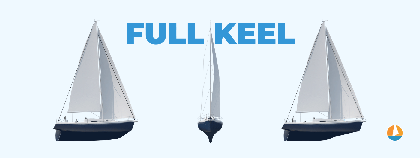
The fin keel is a narrow fin below the boat , usually in the center. It comes with various endings, sometimes with a weight at the tip, adding to the stability, sometimes there are two keels, which helps with performance.
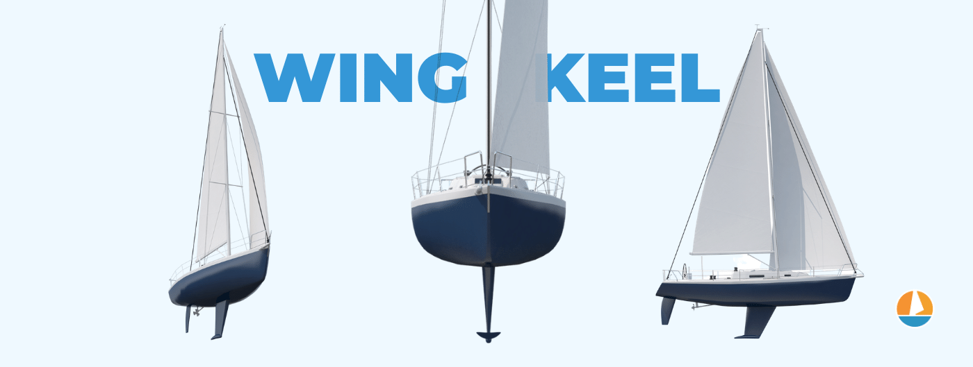
The lifting keel is a fin keel that can be raised . It can be weighted or unweighted , and in some cases they can be lifted all the way, disappearing into the hull. In other cases, they merely lift a bit to gain a more shallow draft.

This is a very rough classification of keel types, and there are plenty more. For a more complete overview, please go over our illustrated guide, which contains a full list of keel types with illustrations and diagrams like the ones above and will help you understand the basics of keel design in ten minutes or less.
In this article, I'll adhere to the three main types of keels, full , fin , and lifting keel.
When it comes to seaworthiness, you need stability to withstand large waves and rougher weathers and either speed to outrun bad weather, or enough rigidity to outlive it.
You want something low maintenance (all things considered) so that it won't be very susceptible to wear and tear and so that it can be repaired with the least amount of tools possible.
On the other hand, you don't have to care much about draft versatility, as you will be mostly in deep waters and you don't need to venture into performance extremes, since racing likely won't be on the menu.
The lifting keel isn't the best bluewater design
Keeping all of the above in mind, we can safely cross off lifting keels in all their variants. They come with too many drawbacks, such as fragility, decreased performance, and less stability provided - for which they offer lesser draft as a trade, but that is a useless feature for bluewater sailors.
The lifting keel design does have its advantages . It is great for navigating shallows. That's why you'll mostly encounter lifting keels among lake sailboats, coastal cruisers, and island hoppers as well as those living in shallow water areas, such as Florida.
Fin keels vs. full keels: both best in their own way
That leaves us with a full keel and a fin keel. And this is where things get tricky. As it turns out, there is no single best answer. Whether you will go with either is up to your preference and sailing style.
Here is what you want to know. If you are a sailor without deadlines, you are in it for the long passages and a lot of time spent on a boat, go with a full keel .
Its extreme amount of wetted surface will contribute positively to stability. The boat will track well and will be less influenced by waves. As far as comfort goes, things won't get any more pleasant (unless you opt for a catamaran).
This means heaving to will be easier, the boat won't rock as much and it will be able to withstand rough weather with as much comfort as possible. In other words, you won't attempt to outrun squalls, since you'll be less likely to, but you'll have a more comfy experience overall.
The reduced heeling is also great, so you can have more sheets up without fearing you will flip your boat and it makes living onboard just a bit more convenient.
All in all, sailing full keels will be more forgiving and easier, as the keel stabilizes both horizontally and vertically. Something noticeable especially when things get bumpy.
As an added bonus, if you happen to run aground, this is the best keel to do so (with perhaps the exception of the swing keel ). Since it is connected to the boat at all its length, there's little chance it will break off.
When looking at full keel designs, you'll notice that the rudder is protected by the keel. So the most vulnerable part of the boat as well as central to boat operation is less likely to get damaged if you run into tricky situations.
So as far as sturdiness goes, this is a win. The side effect is that full keel boats tend to be of sturdier build quality since it's assumed that whoever wants a full keel, opts fundamentally for sturdiness.
In other words, you are buying yourself a slow, steady tank. These designs, often referred to as the traditional, or classical designs, go way back to when technology and materials didn't exactly help the sailors, so they had to go for designs that had their back in all conditions as much as possible, and rely less on technological solutions. This means they have plenty of interesting advantages without the need for gadgets or fancy add-ons.
What are the drawbacks? Speed and maneuverability . There is a reason you don't see full keel racers out there. The keel design creates a lot of drag, slows down the boat, and offers very little in terms of agility.
Also, its fabulous tracking ability, which is so useful when cruising, will prove annoying when maneuvering the boat in smaller spaces, like slips. Getting into slips in marinas will be plenty more difficult than with fin keels since the boat is keen on maintaining direction. So make sure you get those bow thrusters installed.
Then there are fin keels. A common variant is called a bulb keel , which simply means it will have a weight attached to its tip, which increases the righting moment. In other words, it is a counterbalance to reduce heeling.
Another variant is called an L keel , which is shorter to provide a lesser draft, and the sacrificed area is added to the back at the bottom, resulting in an L shape.
Its reduced wetted surface results in lower drag than with full keels, so they are much faster, but they don't track as well and are more susceptible to whatever is happening on the water surface.
Gone are the feeling of safety and sturdiness. Then again, their maneuverability is high, as they don't resist directional change much.
And as you might have guessed, if you run aground with a keel like this, the chances of damage or it full-on ripping out of the boat are considerably higher.
To put it differently, the boat is easier to manipulate, but will not have your back as much when it comes to providing safety. You will need to step your game up and be on guard more than with full keels.
Both these designs are equally capable of withstanding rough weather - though with varying degrees of comfort. They both are capable of long crossings, though one focuses on steadiness, the other on agility.
Luckily, if you dislike either of these, there are hybrids of both, designs that try to get the best of both worlds.
The fin keel variations aren't as plentiful, since sailors have little to complain about when it comes to them. You will find the aforementioned bulb keels that will add to stability - something you will definitely appreciate far from the shore, where the waves get bigger. And there are wing keels, which is a fin keel with horizontal wings connected to its end, to improve directional stability, helping you along when on a long crossing.
When it comes to full keel variations, you will find pretty much anything you can dream of. The variations are mostly in terms of length - they don't necessarily run all the way from the front, all the way to the back, and have varying lengths.
Shortening a full keel lessens the comfort and the heel reducing ability, but works well for speed and maneuverability. And not to lose the rudder protection, some designs feature two keels, as it were, behind one another, where the one in the back is rather small, mostly for the rudder protection, rather than anything else.
If you prefer sturdiness, reliability, comfort, and safety, a full keel is the preferred keel design for bluewater sailing. However, if you value speed, and maneuverability, and don't mind increased heeling with rougher seas, the fin keel design is a good option as well.
And if you like neither, find yourself a compromise of which there are many.
There are dozens of keel designs out there, and each type serves a different purpose and excels under different conditions. To understand which keel type is best for your situation , I recommend you read our Illustrated Guide to Sailboat Keel Types , which contains the fundamentals of keel design and an overview for each keel type's characteristics (including diagrams). It will help you understand which keel designs to consider in ten minutes or less.
Leave a comment
You may also like, 41 sailboat cruising essentials for long trips.
In this post I list the items you are unlikely to have if you have never done bluewater or long-term cruising before. There are some essential safety product and …

The Difference Between Freshwater and Saltwater Boats

Everything You Need to Sail Around the World (by an expert)

What Is Bluewater Sailing?

The Cheapest, Smallest Boat to Sail Around the World
Own your first boat within a year on any budget.
A sailboat doesn't have to be expensive if you know what you're doing. If you want to learn how to make your sailing dream reality within a year, leave your email and I'll send you free updates . I don't like spam - I will only send helpful content.
Ready to Own Your First Boat?
Just tell us the best email address to send your tips to:
Definitions
Length overall (LOA)
Length of water line (lwl)
Length between perpendiculars (LFF)
Rated length
he hull of a yacht is a complex three-dimensional shape, which cannot be defined by any simple mathematical expression. Gross features of the hull can be described by dimensional quantities such as length, beam and draft, or non-dimensional ones like prismatic coefficient or slenderness (length/displacement) ratio. For an accurate definition of the hull the traditional lines drawing; is still a common tool, although most professional yacht designers now take advantage of the rapid developments in CAD introduced in Chapter 1.
In this chapter we start by defining a number of quantities, frequently referred to in yachting literature, describing the general features of the yacht. Thereafter, we will explain the principles of the traditional drawing and the tools required to produce it. We recommend a certain work plan for the accurate production of the drawings and, finally, we show briefly how the hull lines are generated in a modern CAD program.
The list of definitions below includes the basic geometrical quantities used in defining a yacht hull. Many more quantities are used in general ship hydrodynamics, but they arc not usually referred to in the yachting field. A complete list may be found in the International Towing Tank Conference (ITTC) Dictionary of Ship Hydrodynamics.
The maximum length of the hull from the forwardmost point on the stem to the extreme after end (see Fig 3.1). According to common practice, spars or fittings, like bowsprits, pulpits etc are not included and neither is the rudder.
The length of the designed waterline (often referred to as the DWL).
This length is not much used in yachting but is quite important for ships. The forward perpendicular (FP) is the forward end of the designed waterline, while the aft perpendicular (AP) is the centre of the rudder stock.
The single most important parameter in any rating rule. Usually L is obtained by considering the fullness of the bow and stern sections in a more or less complex way.
The maximum beam of the hull excluding fittings, like rubbing strakes.

Fig 3.1 Definitions of the main dimensions
Beam of waterline (bwl)
Displacement
The maximum beam at the designed waterline.
The maximum draft of the yacht when floating on the designed waterline. Tc is the draft of the hull without the keel (the 'canoe' body).
The vertical distance from the deepest point of the keel to the sheer line (see below). Dc is without the keel.
Could be either mass displacement (m) ie the mass of the yacht, or volume displacement (V or V), the volume of the immersed part of the yacht. mc, Vc and Vc are the corresponding notations without the keel.
Midship section For ships, this section is located midway between the fore and aft perpendiculars. For yachts it is more common to put it midway between the fore and aft ends of the waterline. The area of the midship section (submerged part) is denoted AM, with an index 'c' indicating that the keel is not included.
Maximum area section For yachts the maximum area section is usually located behind the midship section. Its area is denoted Ax (AXc).
Prismatic coefficient This is the ratio of the volume displacement and the maximum section (CP) area multiplied by the waterline length, ie CP = V/(AX • Lwl). This value is very much influenced by the keel and in most yacht applications only the canoe body is considered: CPc = Vc(AXc • Lwl). See Fig 3.2. The prismatic coefficient is representative of the fullness of the yacht. The

Circumscribed cylinder volume = v = L^ Ay
Fig 3.2 The prismatic coefficient

BOX WL WL c
Circumscribed box volume =
Fig 3.3 The block coefficient
Block coefficient ( CB)
Centre of buoyancy (B)
Centre of gravity (G)
Freeboard fuller the ends, the larger the Cp. Its optimum value depends on the speed, as explained in Chapter 5.
Although quite important in general ship hydrodynamics this coefficient is not so commonly used in yacht design . The volume displacement is now divided by the volume of a circumscribed block (only the canoe body value is of any relevance) CBc = V J(Lwl • BWL • Tc). See Fig 3.3.
The centre of gravity of the displaced volume of water, its longitudinal and vertical positions are denoted by LCB and VCB respectively.
The centre of gravity of the yacht must be on the same vertical line as the centre of buoyancy. In drawings G is often marked with a special symbol created by a circle and a cross. This is used also for marking geometric centres of gravity. See. for instance, Figs 5.27 or 8.2.
The intersection between the deck and the topside. Traditionally, the projection of this line on the symmetry plane is concave, the 'sheer* is positive. Zero and negative sheer may be found on some extreme racing yachts and powerboats.
The vertical distance between the sheer line and the waterline.
Tumble home
When the maximum beam is below the sheer line the upper part of the topsides will bend inwards (see Fig 3.4). To some extent this reduces the weight at deck level, but it also reduces the righting moment of the
Fig 3.4 Definition of tumble home and flare

Tumble home crew on the windward rail. Further, the hull becomes more vulnerable to outer skin damage in harbours.
Flare The opposite of tumble home. On the forebody in particular, the sections may bend outwards to reduce excessive pitching of the yacht and to keep it more dry when beating to windward.
Scale factor (a) This is not a geometrical parameter of the hull, but it is very important when designing a yacht. The scale factor is simply the ratio of a length (for instance the Lw,) at full scale to the corresponding length at model scale. Note that the ratio of corresponding areas (like the wetted area) is a2 and of corresponding volumes (like displacement) a3.
Lines drawing A complete lines drawing of the YD 40 is presented in Fig 3.5. The hull is shown in three views: the profile plan (top left), the body plan (top right) and half breadth plan (bottom). Note that the bow is to the right.
In principle, the hull can be defined by its intersection with two different families of planes, and these are usually taken as horizontal ones (waterlines) and vertical ones at right angles to the longitudinal axis of the hull (sections). While the number of waterlines is chosen rather arbitrarily, there are standard rules for the positioning of the sections. In yacht architecture the designed waterline is usually divided into ten equal parts and the corresponding sections are numbered from the forward perpendicular (section 0) backwards. At the ends, other equidistant sections, like # 11 and # 1 may be added, and to define rapid changes in the geometry, half or quarter sections may be introduced as well. In Fig 3.5 half sections are used throughout.
The profile is very important for the appearance of the yacht, showing the shapes of the bow and stern and the sheer line. When drawing the waterlines, displayed in the half breadth plan, it is most helpful if the lines end in a geometrically well defined way. Therefore a 'ghost" stem and a 'ghost' transom may be added. The ghost stem is the imagined sharp leading edge of the hull, which in practice often has a rounded stem, and the ghost transom is introduced because the real transom is often curved and inclined. If an imagined vertical transom is put near the real one at some convenient station, it will facilitate the fairing of the lines. The drawing of Fig 3.5 has been produced on a CAD system and no ghost stem is shown. However, a ghost transom is included.
In the body plan, the cross sections of the hull are displayed. Since the hull is usually symmetrical port and starboard, only one half needs to be shown, and this makes it possible to present the forebody to the right and the afterbody to the left. In this way mixing of the lines is avoided and the picture is clearer. Note that in the figure the half stations are drawn using thinner lines.
The above cuts through the hull are sufficient for defining the shape, but another two families of cuts are usually added, to aid in the visual perception of the body. Buttocks are introduced in the profile plan,

* * ^ "i * 2 § 2 II II II II II II II ll II
showing vertical, longitudinal cuts through the hull at positions indicated in the half breadth plan. The diagonals in the lower part of the half breadth plan are also quite important. They are obtained by cutting the hull longitudinally in different inclined planes, as indicated in the body plan. The planes should be as much as possible at right angles to the surface of the hull, thus representing its longitudinal smoothness. In practice, the flow tends to follow the diagonals, at least approximately, so that they are representative of the hull shape as "seen' by the water. Special attention should be paid to the after end of the diagonals, where knuckles, not noticcd in the other cuts, may be found, particularly on lOR yachts from the 1970s and the 1980s. Almost certainly, such unevenncss increases the resistance and reduces the speed of the yacht.
The other line in the lower part of the half breadth plan is the curve of sectional areas, representing the longitudinal distribution of the submerged volume of the yacht. The value at each section is proportional to the submerged area of that section, while the total area under the curve represents the displacement (volume). A more detailed description of the construction of the curve of sectional areas will be given in Chapter 4.
In order to define exactly the shape of the hull a table of offsets is usually provided by the designer. This is to enable the builder to lay out the lines at full size and produce his templates. Offsets are always provided for the waterlines, but the same information may be given for diagonals and/or buttocks also. Note that all measurements are to the outside of the shell.
The drawing should be made on a special plastic film, available in different thicknesses. The film is robust and will not be damaged by
Photo 3.6 Tools (triangle, plastic film, straight edge, brush, pens, pencil, erasing shield and eraser)

Photo 3.7 Tr¿\nster of measures from body plan (top) to half breadth plan (bottom) using a paper ribbon

erasing. Furthermore, it is unaffected by the humidity of the air. which may shrink ordinary paper.
Since the film is transparent the grid for the lines drawing is drawn on the back so that it will remain, even after erasing the hull lines on the front many times. Great care must be exercised when drawing the grid, making sure that the alignment and spacing are correct and that all angles arc cxactly 90°. In Fig 3.5 the grid is shown as thin horizontal and vertical lines, representing waterlines, buttocks and stations.
Black ink should be used when drawing the grid and preferably when finishing the hull lines also. However, when working on the lines a pencil and an eraser are needed. There are, in fact, special pencils and erasers for this type of work on plastic film. An erasing shield and a brush are also most useful (see Photo 3.6).
For creating the grid a long straight edge is required, together with a
Photo 3.8 Ducks and a spline used for drawing a water Iine

Photo 3.9 Templates used for drawing lines with large curvature

large 90° set square. It is very convenient to have a bunch of paper ribbons, which can be used for transferring different measures from one plan to the other. For example, when drawing a waterline the offsets of this line may be marked on the ribbon directly from the body plan and moved to the half breadth plan (Photo 3.7).
To draw the hull lines it is necessary to have a set of splines and weights or ducks. Long, smooth arcs can be created when bending the splines and supporting them by the ducks at certain intervals. Photo 3.8 shows how these tools are used when drawing a waterline. The splines should be made of plastic, somewhat longer than the hull on the drawing, and with a cross-section of about 2.5 mm2. Many different types of ducks can be found, some of them home made. Preferably,

Photo 3.10 PI an i meter they should be made of lead, and the weight should be between 1.5 and 2.5 kg. To be able to support the spline, they should have a pointed nose, as shown in Photo 3.8.
The splines are needed when drawing the lines in the profile and half breadth plans. However, the lines of the body plan are usually too curved for the splines, so it is necessary to make use of a set of templates especially developed for this purpose. The most well known ones are the so called Copenhagen ship curves, the most frequently used of which are shown in Photo 3.9.
A very convenient instrument, well known in naval architecture, is the planimeter, used for measuring areas (see Photo 3.10). The pointer of the planimeter is moved around the area to be measured, and the change in the reading of the scale when returning to the point of departure gives the area enclosed by the path followed. Considering the difficulty in following exactly any given line the accuracy is surprisingly high, more than adequate for the present purposes. The need for measuring areas will be explained in the next chapter.
Since many calculations have to be carried out when preparing the drawings, and indeed in the whole design process, an electronic calculator is essential. A simple one would be sufficient in most cases, but a programmable calculator would simplify some of the calculations, particularly if a planimeter is not available. Most scientific calculators have programs for calculating areas with acceptable accuracy, and programs are available for most of the calculations described in the next chapter.
Designing the hull is a complex process, and many requirements have to be considered. One difficulty is that important parameters, such as the displacement cannot be determined until the lines have been fixed. This calls for an iterative method. Such a method is also required in the fairing of the lines. The problem is to make the lines in one projection correspond to smooth lines in the other two projections. For an inexperienced draftsman this problem is a serious one, and many trials may be needed to produce a smooth hull.
While the preferred sequence of operations may differ slightly between yacht designers the main steps should be taken in a certain order. In the following, we propose a work plan, which has been found effective in many cases. It should be pointed out that the plan does not take into account any restrictions from measurement rules.
Step 1: Fix the main dimensions These should be based on the general considerations discussed in Chapter 2, using information on other yachts of a similar size, designed for similar purposes. This way of working is classical in naval architecture, where the development proceeds relatively slowly by evolution of previous designs. It is therefore very important, after deciding on the size of the yacht, to find as much information as possible on other similar designs. Drawings of new yachts may be found in many of the leading yachting magazines from all over the world.
The dimensions to fix at this stage are: length overall, length of the waterline, maximum beam, draft, displacement, sail area, ballast ratio, prismatic, coefficient and longitudinal centre of buoyancy. One of the aims of this book is to help in the choice of these parameters and to enable the reader to evaluate older designs when trying to find the optimum for his own special demands.
Step 2: Draw the profile As pointed out above, this step takes much consideration, since the aesthetics of the yacht are, to a large extent, determined by tBfe pi^ffle-
Step 3: Draw the midship section The midship section can be drawn at this stage, or, alternatively, the maximum section if it is supposed to be much different. This may occur if the centre of buoyancy is far aft. The shape of the first section drawn is important, since it determines the character of the other sections.
Step 4: Check the displacement To find the hull displacement calculate (or measure) the submerged area of the section just drawn and multiply by the waterline length and the prismatic coefficient chosen for the hull. From the ballast ratio, the keel mass can be computed and the volume can be found, dividing by the density of the material (about 7200 kg/m3 for iron and 11300 kg/m- for lead). Assume that the rudder displacement is 10% of that of the keel and add all three volumes. If the displacement thus obtained is different from the prescribed one, return to step 3 and change accordingly.
The procedure described is for a fin-keel yacht. For a hull with an integrated keel, as on more traditional yachts, the prismatic coefficient usually includes both the keel and the rudder.
Step 5: Draw the designed waterline One point at or near the midship station is now known, together with the two end points from the profile, so now a first attempt can be made to draw the designed waterline.
Step 6: Draw stations 3, 7 and the transom The waterline breadth is now known, as well as the hull draft, and the sections should have a family
resemblance to the midship section. Often it is helpful to draw a ghost transom behind the hull.
Step 7: Draw new waterlines Two or three waterlines can now be drawn above and below the DWL. If the appearance is not satisfactory, go back to step 6 and change.
Steps 8 and 9: Add new sections and waterlines
Once this is done, sections I-9 should be completed as well as 7-10 waterlines. Constant adjustments, have to be made in order to create smooth lines in the body plan, as well as in the half breadth plan.
Step 10: Recheck the displacement and the longitudinal centre of buoyancy The curve of sec tional areas can now be constructed. Its area gives the displacement (excluding that of keel and rudder) and its centre of gravity corresponds to the longitudinal position of the centre of buoyancy. If not correct, adjustments have to be made from steps 5 or 6,
Step 11: Draw diagonals Inspect the smoothness, particularly near the stern. Adjust if necessary.
Step 12: Draw buttocks This is the final check on the smoothness. Usually only very minor corrections have to be made at this stage.
Computer aided design of hulls
As mentioned in Chapter 1, most CAD programs use master curves for generating the hull surface. Each curve is defined by a number of points, called vertices. Photo 3.11 shows, in a plan view, the grid of master curves used for generating the YD-40 hull. One of the transverse curves has been selected in Photo 3.12 and it can be seen how the smooth hull surface is generated inside the curve, which is shown as piece-wise linear between the vertices.
Photo 3.11 Grid of master curves used for the YD-40 (the vertical line to the right marks the origin of the coordinate system)
Photo 3.12 A section with vertices (crosses), master curve (between the crosses), hull surface and cuwature (outermost line)

The task of the designer is to specify the vertices in such a way that the desired hull shape is created.There are different ways of achieving this. Some programs start from a long cylindrical body or a box, while others start from a flat rectangular patch, defined by an orthogonal grid. These original shapes are then distorted by moving the vertices around, and it is relatively easy to produce a yacht-like body. However, it takes experience and experimentation to obtain a shape that satisfies criteria set up beforehand. In practice, designers very seldom start from scratch, but work from earlier designs, which already have a desirable shape and a known grid of master curves surrounding it. Since most new designs are evolutions of previous ones this approach is very natural.
A problem encountered when the first CAD programs for yachts appeared was that the scale on the screen was too small, and the resolution too low to enable the designer to create fair lines. Small bumps on the surface could not be detected 011 the screen, and it sometimes happened that the bumps were noticed only after the start of the hull construction . Therefore the CAD program developers introduced plots of the curvature of lines on the hull. Such a plot is shown.in Photo 3.12. The curvature of the line, which essentially corresponds to a section, is almost constant, except at the ends where it goes to zero.
Photo 3.13 illustrates the sensitivity of the curvature to small changes of the surface. The sheer line is shown in a plan view. In the top photo (the real design) the curvature is smooth and relatively constant along the hull. In the bottom photo one vertex point has been moved 10 mm at full scale perpendicular to the surface. The resulting change in the sheer line is so small that it cannot be detected by eye, but the curvature exhibits a considerable bump and some smaller fluctuations, showing that the line is not smooth. By looking at the curvature, lines may thus be generated that look fair even at full scale.
Photo 3.13 Sheer line with vertices and curvature. (top) Real design. (bottom) One vertex point moved 10 mm

Photo 3,14 Perspective view A great advantage of most CAD programs is that the hull may be of the YD-40 shown in perspective. As pointed out in Chapter 1 it is important to study the sheer line in particular from different angles, since the impression of the hull contour in reality is also influenced by the beam distribution, which is not visible if only the profile view is studied. Fig 3.14 shows the YD-40 in perspective, and a good impression can be obtained of the shape. "
By using a CAD program a fair hull can be produced rapidly and different requirements may be satisfied without too much work, such as a given prismatic coefficient or longitudinal centre of buoyancy. Meeting such requirements accurately in a manual process is extremely time consuming, so it is understandable that CAD techniques are always used nowadays by professional designers. However, due to the considerable cost of a CAD system, most amateur designers will still have to use the manual approach described above.
Continue reading here: Hydrostatics And Stability
Was this article helpful?
Recommended Programs

Myboatplans 518 Boat Plans

Boat Alert Hull ID History Search

3D Boat Design Software Package
Related Posts
- Methodology - Ship Design
- Plan Drawing Fregatt - Rigging
- Hull Construction - Ship Design
- Catamaran Design Guide - Catamarans Guide
- LOD and LOA - Cruising Sailboats Reference
- Hull Hydrodynamics and Design
Readers' Questions
How to figure the width to height to length of a yacht?
To figure out the width, height, and length of a yacht, you typically need to refer to the yacht's specifications provided by the manufacturer, yacht designer, or owner. These specifications should include the appropriate measurements. Consult the yacht's specifications: Look for the official documentation or technical information provided for the yacht. This documentation usually includes the length, width, and height of the yacht, referred to as LOA (Length Overall), Beam, and Draft, respectively. The specifications are usually available in brochures, user manuals, or on the official website of the yacht manufacturer. Seek professional advice: If you cannot find the specifications yourself or need more specific information, consider reaching out to yacht brokers, yacht builders, naval architects, or other professionals in the yachting industry. They have extensive knowledge and can guide you with accurate measurements or provide information by using the yacht's model or brand. Measure the yacht yourself: If you have physical access to the yacht and cannot find the specifications through other means, you can measure it directly. However, this method is less accurate and should only be used as a last resort. Use a measuring tape or other appropriate tools to measure the overall length, width or beam, and height. Ensure to measure from fixed reference points for consistency and accuracy. Remember that yachts come in various sizes, designs, and layouts. The width or beam, for example, may be different at different points along the vessel's length due to design variations. It is essential to refer to the official specifications or seek professional advice for the most precise and reliable measurements.
Can you use geometry on boats?
Yes, geometry can be applied to various aspects of boats, particularly in the design and construction phase. Here are a few examples: Hull Design: Geometry is crucial in designing the shape and dimensions of a boat's hull. The angles, curves, and mathematical calculations are used to ensure stability, hydrodynamics, and buoyancy. Stability Analysis: Geometry is used to determine the center of buoyancy, center of gravity, and metacenter of a vessel. These calculations are essential for assessing a boat's stability, both at rest and in motion. Navigation and Bearings: Geometric concepts such as angles, triangles, and trigonometry are used to calculate headings, course corrections, and bearings while navigating a boat. Sail Measurement and Adjustments: Sailboats utilize various geometric principles to determine sail sizes, aspect ratios, and shapes. The geometry of sail adjustments, such as tightening or loosening the sail, can affect the boat's speed and performance. Nautical Charts: Geometry plays a vital role in nautical charting, which involves representing the Earth's curved surface on a flat chart. Projections, grid systems, and coordinate systems are employed to accurately depict and navigate waterways. These are just a few examples of how geometry can be applied to boats. Overall, geometry is critical in ensuring boat design, navigation, and performance, making it an important aspect of the boating industry.
How to find ship displacement from submerged area?
To find the ship displacement from submerged area, you can follow these steps: Determine the underwater or submerged area of the ship. This can be done by calculating the area of the ship's hull that is below the waterline when it is fully submerged. Convert the area into a volume by multiplying it by the ship's beam (width) or mean draft (depth). Multiply the volume by the density of the water. The density of water varies slightly depending on temperature and salinity, but a typical value is around 1,000 kilograms per cubic meter. The result of this calculation will be the ship's displacement. It represents the weight of the water displaced by the ship when it is fully submerged. Note: This method assumes that the ship's hull has a constant shape below the waterline. In reality, the shape may vary, especially towards the ends of the ship.
How to draw a simple ship?
To draw a simple ship, follow these step-by-step instructions: Start by drawing a horizontal line slightly curved at the ends to create the ship's hull. Add a smaller curved line above the hull to outline the ship's deck. At the front of the ship, draw a triangular shape for the bow. On top of the deck, draw a small rectangular structure or cabin. Add a flagpole at the back of the deck by drawing a long, thin rectangle. Draw a small rectangle or square at the top of the flagpole for the flag. Next, add a slightly curved line near the waterline for the keel of the ship. On both sides of the hull, draw a series of diagonal lines to create the ship's planking. To indicate windows or portholes, draw small oval or circular shapes along the cabin. Add a couple of mast poles on the deck. To do this, draw two vertical lines with a horizontal line connecting them at the top. On top of the mast poles, add triangular or rectangular shapes for the sails. Finally, erase any unnecessary guidelines, and you can add more details like waves or seagulls to complete your simple ship drawing. Remember, this is just one way to draw a simple ship. Feel free to modify the design or add additional elements to make it your own!
How to draw a pin keeldrawing tutorialtop keel?
To draw a pin keel, follow these steps: Begin by drawing a slightly curved horizontal line. This line will serve as the water surface. Next, draw a long vertical line that will represent the keel. The keel should start at the bottom of the water surface line and extend downward. At the bottom of the vertical line, draw a slightly curved horizontal line. This line will represent the lower part of the keel. On the left side of the keel, draw a diagonal line extending outward. This line will represent the forward part of the keel. Repeat the previous step on the right side of the keel, drawing a diagonal line to represent the aft part. Connect the ends of the diagonal lines with a curved line, forming the bottom part of the keel. Add additional detail to the keel by drawing a small horizontal line near the top. This line represents the top part of the keel. Finally, erase any unnecessary lines and add shading to give the keel more depth and dimension. Remember to take your time and practice as much as needed to improve your drawing skills.
How do you draw a ship?
Drawing a ship can be a fun and creative process. Here's a step-by-step guide on how to draw a ship: Start by drawing a long, slightly curved horizontal line in the center of your paper. This line will serve as the ship's waterline. From one end of the waterline, draw a slanted rectangle shape, slightly wider at the bottom than the top. This will be the ship's hull. At the other end of the waterline, draw a smaller rectangle shape, slightly tilted upward. This will be the ship's bow. Connect the bow and the hull with two diagonal lines, creating the ship's front structure. Add a large, slightly curved rectangle shape at the top of the hull. This will be the main deck of the ship. Draw a smaller rectangle shape above the main deck to represent the ship's superstructure. Sketch two parallel, slanted lines on the front of the ship's superstructure to create the pilot house. On the main deck, draw a few rectangular shapes to indicate windows or portholes. Add details like railing, stairs, and lifeboats on the sides and top of the ship as desired. Extend the hull below the waterline using a curved line to give the ship depth. For the finishing touches, you can draw some waves around the ship, seagulls in the sky, or a flag on top. Remember to be creative and modify the design as you like. Don't worry if your drawing doesn't turn out perfect at first; practice makes perfect!
What hull curves do yachts fallow is it x squared?
The hull curves of yachts can vary depending on the design and purpose of the yacht. While some yacht hulls may follow a curve that resembles the function of x squared, others may follow different curves such as parabolic curves, ellipses, catenary curves, or other mathematical shapes. The specific curvature of a yacht's hull is determined by factors such as the desired speed, stability, maneuverability, and hydrodynamic efficiency of the vessel. It is typically designed by naval architects and engineers who consider various factors including the size and weight distribution of the yacht, the intended use (e.g., racing, cruising, etc.), and materials used in construction. In summary, while some yachts may have hull curves similar to x squared, there is no universal standard hull curve for all yachts. The hull design depends on various factors and can incorporate different mathematical curves to achieve specific performance characteristics.
How to calculate the curvature of a boat?
To calculate the curvature of a boat, you would need to determine the radius of its curvature. The curvature refers to the degree of how much the boat's hull curves or bends. Gather the measurements: You will need the length and width measurements of the boat. These measurements can be obtained from the boat's specifications or by physically measuring it. Determine the midpoint: Locate the midpoint of the boat's length. This can be done by dividing the boat's length measurement by 2. Measure the rise: Starting from the midpoint, measure the distance between the bottom of the boat's hull and a straight line connecting the bow and stern (i.e., the rise). Measure the run: Measure the distance between the midpoint and the bottom of the boat's hull at the bow and stern. Calculate the radius of curvature: The radius of curvature can be calculated using the following formula: Radius = (run^2 + rise^2) / (8 x rise). The curvature: The curvature is calculated as the reciprocal of the radius of curvature. It's important to note that this calculation assumes a boat's hull shape can be represented by a simple section of a circle. More complex hull shapes, such as those with multiple curves or irregular shapes, may require different mathematical models or numerical methods to accurately determine curvature.
How to measure the curveture of a boat hull?
There are several methods to measure the curvature of a boat hull. Here are three common techniques: Profiling: This method involves taking measurements at specific points along the hull's surface to understand the curvature. You can use a flexible measuring tape or string to measure the distance from the hull to a straight reference line at different points along the boat's length. These measurements can then be plotted on a graph to depict the curvature of the hull. Reflection Method: For this technique, you need a laser level and a measuring tape. Firstly, position the laser level at a fixed distance from the boat hull and horizontally direct the laser beam towards the hull. The laser beam will be reflected back from the hull surface. Measure the distance from the laser level to the hull at different points along the boat's surface. These measurements can be used to calculate the curvature of the hull. 3D Scanning: Utilizing modern technology, you can use a 3D scanner to create a digital model of the boat hull. The scanner emits laser beams or projects structured light patterns onto the hull, capturing its shape in detail. The resulting 3D model can then be used to measure the curvature of the hull accurately. It is important to note that measuring the curvature of a boat hull may require specific tools and expertise. Hence, it is advised to consult with industry professionals or specialists for accurate measurements.
How to draw a yacht keel?
To draw a yacht keel, you can follow these steps: Start by drawing a horizontal line on your paper. This line will serve as the waterline. From the center point of the waterline, draw two vertical lines going downward to create the main part of the keel. These lines should taper towards the bottom. At the bottom of the keel, draw a horizontal line connecting the two vertical lines. This will form the bottom edge of the keel. Now, draw a diagonal line on each side of the keel, starting from the top and curving slightly outward. These lines will form the shape of the keel as it narrows towards the top. Connect the ends of the diagonal lines at the top with a smooth curve to create the rounded shape of the keel. Next, draw horizontal lines across the keel to represent the different sections or layers. These lines can be evenly spaced or closer together at the top and gradually getting wider towards the bottom. Add details such as ribbing or reinforcements by drawing diagonal lines across the keel, intersecting the horizontal lines. To give the keel a more realistic look, you can shade the bottom part and add some shadow where it meets the waterline. Finally, you can add additional details such as a bulbous bow or a fin at the bottom of the keel based on the specific design of the yacht you are drawing. Remember to sketch lightly at first and gradually darken your lines as you refine the shape. And don't forget to have fun and experiment with different styles and variations to make your drawing unique!
How to draw a boat into transverse stations?
Drawing a boat into transverse stations can be done by following these steps: Start by selecting a suitable scale for the drawing. This will depend on the size of the boat you want to draw and the size of the paper or canvas you are using. Begin by drawing a horizontal line across the paper, representing the waterline. Next, draw vertical lines representing the transverse stations at regular intervals along the waterline. These lines should be evenly spaced and represent the cross-sections of the boat at different points along its length. Use reference drawings or images of the boat to guide your drawing. Start by drawing the outline of the boat's hull within each station. Pay attention to the curvature and tapering of the hull as it moves towards the bow and stern. After drawing the outline, add any additional details such as deck lines, windows, hatches, and other features of the boat. Use shading techniques to add depth and dimension to the drawing. Pay attention to the light source and add shadows accordingly to create a realistic representation of the boat. Finally, go over your drawing and make any necessary adjustments or corrections to ensure accuracy.
What is nonprismatic hull?
A nonprismatic hull is a type of hull shape in naval architecture that does not conform to the standard prismatic shape of traditional sailing vessels. Nonprismatic hulls are designed to increase performance in certain areas such as speed and efficiency, as well as to reduce drag and enhance maneuverability. Nonprismatic hulls are also often used as part of a wave piercing design to cut through wave crests, thus reducing the size of the wake behind the ship.
How to design a schooner hull?
Research the history of schooner hulls and their design features. This will help you understand the shipbuilding principles and methods used in their construction. Consider the type of schooner you want to design. Is it a racing vessel or a cruising boat? This will help you determine the size, weight and other characteristics of the hull. Consider the type of material you will use for the schooner. Traditionally, schooner hulls have been made of wood or fiberglass, but there are other materials that can be used as well. You need to choose a material that meets your needs and budget. Work with an experienced maritime designer or drafter to create a 3D model of the schooner hull. This will help you visualize the hull and make sure it meets your specifications. Have a qualified shipwright or boat builder construct your schooner. Ensure that the schooner is tested and certified by a naval architect before you take it out on the water.
How to draw hull lines plan from boat existing images in reverse engineering?
Take a picture of the boat's existing lines plan. Import the image into a vector graphic program such as Inkscape, Adobe Illustrator, or Corel Draw. Trace the contours of the boat's hull using the Pen Tool or other trace tool in the program. Adjust the lines to make sure they accurately represent the boat's shape and contours. Once the lines plan is complete, use a ruler to draw perpendicular lines from the boat's existing lines plan as a reference for the hull. Use the curved line tool to refine the shape of the hull and make sure everything is in proportion and accurate. Double-check to make sure the hull lines plan is correct, and save the file for future reference.
What does half a sideways figure eight mean on a ship drawing?
Half a sideways figure eight on a ship drawing typically denotes the ship's waterline—the line where the ship sits in the water.
How to work out the shape and profile of a yatch datum line?
Establish the design criteria and parameters of the yacht. This should include the length, width, height and any other characteristics relevant to the design of the yacht. Define the design goals and objectives of the yacht, including the purpose and function of the yacht, how it will be used, and what type of sailing or other activities will take place on it. Choose an appropriate hull shape and size for the yacht based on the design criteria, goals and objectives. Create a 3D computer model of the yacht design, incorporating the appropriate hull shape and size. Use the model to define a datum line for the yacht, which will help to accurately measure the craft's performance and characteristics. The datum line should run from the center of the waterline around the hull to the transom. Using the 3D model, define the profile of the yacht by “lofting” the curves of the hull and the deck. Refine the design by adjusting the curves of the hull and deck to ensure that the yacht's performance characteristics are maximized. Use the computer model to run “virtual wind tunnel” tests on the design, to ensure that its performance characteristics are optimized.
How to draw a boat on water?
Start by sketching the basic shape of the boat. Start with a long, rectangular shape to form the hull of the boat. Add a slight curve to the top of the boat to give it an authentic boat shape. Draw a smaller rectangular shape for the cabin of the boat. Sketch two triangular shapes on the left and right side of the cabin for the sails. Draw a series of small circles along the bottom of the boat to create the waterline. Now add the details to your boat: windows, doors, life preservers, etc. Finally, draw some small waves around the boat to create the illusion of the boat sailing on water.
What are fair lines and sheer lines of a yacht?
Fair lines are the contours of the yacht's hull. Sheer lines are the long, gradual arch of the deck, starting at the bow and extending to the stern.
How to draw a hardshine boat hull quickly?
To draw a hardshine boat hull quickly, you can follow these steps: Start by drawing a horizontal line to represent the waterline. This line will serve as the base for the boat hull. Sketch a rough outline of the boat hull shape above the waterline. Keep in mind that hardshine boat hulls are typically streamlined and have a sharp, angular shape. Add a slightly curved line below the waterline to depict the bottom part of the hull. The curve should be gentle and gradually merge into the horizontal waterline. Extend two diagonal lines downward from the front end of the boat hull to create the bow. The bow should be pointed and sharp to cut through the water efficiently. Add a small transom at the rear end of the boat hull. The transom is usually flat or slightly curved upward. Sketch two straight lines from the bow to the stern to represent the deck of the boat. Draw a horizontal line across the middle section of the hull to indicate a separation or border between the upper and lower parts. Add details to the hull, such as chines (angled lines along the sides of the hull) and spray rails (small fins or ridges). These elements contribute to the boat's stability and improve its performance in the water. Shade the lower portion of the hull with a darker tone to emphasize the hardshine effect. Use quick and light strokes to achieve a glossy appearance. Finally, erase any unnecessary guidelines and refine the drawing as needed. Remember, practicing and experimenting with different techniques will help you improve your drawing skills and speed over time.
How to measure a ships hull shape from inside?
One way to measure a ship's hull shape from inside is by using 3D laser scanning. This technique uses lasers to take precise measurements of a ship's inner hull shape. The lasers scan around the interior of the ship and create a 3D image of the ship's shape. This data can then be used to create a precise and accurate measure of the ship's hull shape.
How to lay out a lines drawing for displacement hulls?
Start by drawing the waterline at the mid-point of the vessel. Draw the bow from the top of the waterline to the nose of the vessel. Draw the stern from the bottom of the waterline to the end of the vessel. Draw in all of the chines of the vessel, the curved lines along the bottom of the sides of the boat, at the waterline. Draw in any other details such as the upturned bow, the tail, or any other details that the vessel may have. Draw the sheer line and the sheer forward, running along the top of the vessel and curving inwards and downwards in the center. Add in any additional lines needed to complete the displacement hull. Use a protractor to make sure all of the angles are correct. Use a ruler to draw the exact lines and make sure the lines are the correct length.
- OC Wally Cento
- 84 Mini Maxi
- IMOCA Open 60
- Consultancy Services
- 30m Blue Water Cruiser
- 25m Explorer Yacht
- 24m Fast Cruising Catamaran
- 23m Performance Cruiser
- 20m Explorer Yacht
- 20m High Performance Cruiser
- 18m Blue Water Cruiser
- 15m Performance Cruiser
- 15m Explorer Yacht
- 12m Explorer Yacht
- Multihull Design
- 18m Explorer Yacht
- 40m Blue Water Cruiser
- 40m Cruiser Racer
- 33m Performance Cruiser
- 30m Wally Cento
- 24m ORCsy Racer Cruiser
- 24m Day Sailer
- Carbon Component Design
- Yacht Performance Development
- CFD and Model Testing
- Twin Rudder Steering Systems
- Custom Deck Hardware
- Modifications and Refit
- VPP Routing and Sail Analysis
- Classic Yacht Refit & Optimisation
- Naval Architecture
- Engineering
- Rudder Design
- Brokerage Services
- 'Seahorse Magazine' #192
- Lucent #180
- Influence #171
- 'Eora' #169
- 'The Three Brothers' #168
- 'Edenred' #165
- Polka Dot #154
- 'Teata' #148
- ‘Sensei’ #131
- 'Sabre II' #93
- French Pineapple #79
- 'Letto Di Pletto' #47
- 'Mowgli' #41
- 23.8m Ultime Trimaran
- 20.7m Orma Trimaran
- 18.28m Orma Trimaran
- 16.75m Cruising Catamaran
- 16.1m Cruising Catamaran
- 12.8m Crowther Shockwave Catamaran
- 9.1m Seacart 30 Trimaran
- 26.3m Aluminium Sloop
- 22.38m Aluminium Classic Yacht
- 21.0m Steel Schooner
- 21.0m Aluminium Cruising Ketch
- 20.0m Aluminium Explorer Yacht
- 20.0m Luca Brenta Racer Cruiser
- 19.6m Aluminium Bluewater Cruiser
- 19.2m Aluminium Lifting Keel Sloop
- 18.23m Mylius Racer Cruiser
- 16.0m Sly Cruiser Racer
- 14.5m Aluminium Cruising yacht
- 13.87m Wooden Motor Sailer
- 11.6m Classic Pilot Cutter
- 25.25m Reichel Pugh Maxi
- 18.28m IMOCA 60 One Planet
- 18.28m O Canada IMOCA Open 60
- 18.28m Come in Vendee Open 60
- 18.23m Mylius FD Racer Cruiser
- 15.84m TP52 Racing Yacht
- 15.25m Pegasus Open 50
- 10.89m Figaro 3
- 10.1m Figaro 2
- 14.5m Aluminium Cruising Yacht

Robb Report
8 Fascinating Facts About ‘Kokomo,' the Lightning-Fast 192-Foot Sailing Superyacht
Posted: March 15, 2024 | Last updated: March 15, 2024

2.-SY-Kokomo_Sailing_1-064
The 192-foot Kokomo was the second largest sloop in the world when it launched from New Zealand’s Alloy Yachts shipyard in 2010. It remains the largest fast-cruising sloop available for charter. The yacht’s commissioning owner Lang Walker (who died in January 2024) was a seasoned sailor who gave all three of his yachts the same name.
The first was a 131-foot sloop, which Walker replaced five years later with a 171-footer. The same day he took delivery of his 171-foot sloop, he placed an order for the third and final 192-foot Kokomo, which he planned to use for racing and cruising around the world. He also kept the same design team for all three yachts, with exterior and naval architecture by Ed Dubois and interior by UK’s RWD.
The reference to the yacht’s name has had different explanations over the years, ranging from the pseudonym of a composer whose music Walker played as a child to a nod to the Beach Boys’s song from their 1988 album Still Cruisin’, which references a fictional utopian island called Kokomo. The island fantasy was brought to life in 2011 when Walker acquired a private island in Fiji’s Great Astrolabe Reef and named it Kokomo.
Here are eight unknown facts about one of the most game-changing sailing yachts on the water.

You’re Going to Need a Bigger Boom
When Kokomo was launched, she was the second-largest sloop in the world and carried the largest set of sails made by Doyle Sails in New Zealand. The 23,971-square-foot asymmetric spinnaker is half the size of a professional football field, while the 9,688-square-foot mainsail needs a crane to lift it. Because of the gargantuan size of the sails, the designers entered a new era of spar and winch design, having to “reinvent” the deck equipment—winches, mast, boom, rigging and sails—to cope with the 31.6-ton load on the genoa sheet and 32-ton load on the main sheet clew. The 244-foot carbon mast is the largest ever made by Southern Spars.

A Hidden Lifting Keel
The yacht’s 130-ton lifting keel is one of its most impressive features, though it’s largely left to the imagination. The interior layout is carefully designed so that the keel structure remains hidden. Dubois Naval Architects positioned the keel box to come above the main deck, serving as a partial separation between the bridge and the main salon (see inset). Kokomo was only the second yacht to be fitted with a lifting a keel, the first being 246-foot M5 (ex-Mirabella V), the world’s largest single-masted sailing yacht. This innovative design shortens Kokomo’s 28.5-foot draft when the keel is fully extended, to just 15 feet for shallow waters.

Now You See It, Now You Don’t
Kokomo might be big on technology, but never at the expense of design. The wheelhouse has fold-down computer screens that conceal the navigation equipment when not in use, converting to beautiful carbon counter tops. This design sleight of hand transforms a highly technical area into a tony lounge. It’s a theme that extends to the foredeck, where the yacht’s two tenders are concealed in dedicated lockers. There’s also a fully retractable tender crane that launches the tenders from either side of the boat but disappears out of sight when guests are using the Jacuzzi. “The designated deck lockers were an advanced feature at the time of her launch,” says Wynne, adding that another bonus is that diesel tanks are fully available. “The tenders can be fueled onboard before launching.”

It Takes Just A Few Good Sailors
Kokomo can accommodate up to 10 crew in total, but theoretically it only takes two to sail—a helm person and a sail trimmer. That sounds almost impossible given the size and complexity of yacht. But all sails are controlled by joystick on the flybridge. And when the boat is in full-on racing mode, there are control stations on both sides, providing visibility of the sails. Thanks to the hydraulics system, the mainsail can be hoisted and lowered on a wireless remote control. Of course, maneuvers like stowing the massive genoa can never be automated. That’s a job for a half-dozen good sailors.

Art On Board
The hallway that leads to the owner’s cabin is lined with a mosaic tapestry made from sea glass woven together with wire. Backlit to create an unusual effect, it’s just one of the eclectic works of art that decorates the interior. The main salon also has a stunning and colorful work of glass art as another example.

Interior Matters
Kokomo is not all tech features. The yacht’s modern interiors combine dark wood floors and calming cream furnishings start in the main salon and continue across the five guest cabins. Penned by British studio Redman Whiteley Dixon, the design carefully wraps around the lifting keel without sacrificing or impeding on any interior guest space. The yacht accommodates up to 10 guests in a master suite, VIP, one double cabin and two twins. There are other accommodations for up to 10 crew. On the foredeck, the Jacuzzi brings another element of outdoor entertainment, bolstered by a sunken cockpit.

World Traveler
The mandate issued by Walker was to create a yacht that was a “quantum leap forward” from his previous yachts, with superior sailing characteristics and guest comfort. The mast’s height is too tall to sail through the Panama or Suez Canals, which meant it would have to be designed to sail around Cape Horn and the Cape of Good Hope to reach the Caribbean and Mediterranean. The maiden voyage took the yacht from the New Zealand shipyard to Australia, New Caledonia, the Solomon Islands, and Fiji. It also spent time at Walker’s private island (pictured above), also named Kokomo. The vessel has since spent many years exploring the Caribbean and Med. It’s based in both regions during the respective cruising seasons, with charters available through Cecil Wright.
More for You
Aileen Cannon's 'Insane' Donald Trump Filing Trashed by Legal Experts
Charlie Munger lived in the same home for 70 years: Rich people who build 'really fancy houses' become 'less happy'
US is seeing a ‘Bidenvasion of epic proportions’: Missouri AG Bailey
"When I was a kid, David Robinson wasn't very nice to me" - Kobe Bryant on why Shaquille O'Neal badly wanted to torch the Spurs
Opinion: What I've learned about living alone after losing my wife of 42 years
The Tesla Cybertruck Engineering Teardown Is Finally Happening
Insurance Company Places Massive Bet on Trump’s Defamation Appeal Bond
3 things to never do at work, according to an HR professional with 10 years' worth of experience
Federal appeals court blows up Biden's carbon emissions disclosure rule
10 States Americans Are Leaving in Droves and 5 States They Are Moving To
Scientists Think They've Found a New Cause of Type 2 Diabetes
Drone images taken deep inside melted Fukushima nuclear reactor show damage
Trump’s mixed-up, invented and false account of his first impeachment
Keep this line off your resume, says ex-Disney recruiter: ‘There's zero benefit’
Picture Shows Kyrie Irving Stepped Out Of Bounds Before Hitting Game-Winner Over Nikola Jokic
‘Multiculturalism’ is damaging our society. There is only one way to stop it
Jan. 6 defendant got 2 congressional internships after she allegedly breached the building
Fact Check: About That 'Russian Media' Video of Supposed Nuclear Attack on US
Three potential landing spots for Bills WR Stefon Diggs
All the ex-Trump officials who refuse to endorse him in 2024

First refuelling for Russia’s Akademik Lomonosov floating NPP
!{Model.Description}
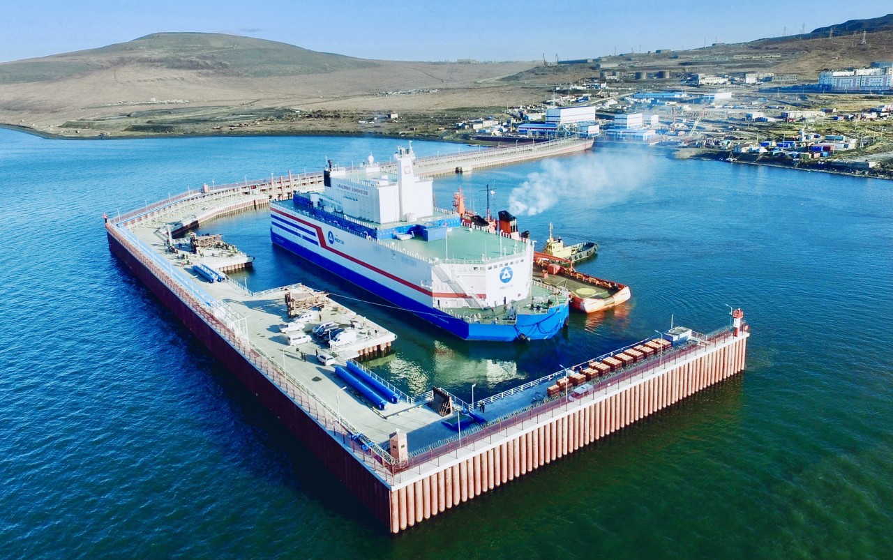
The FNPP includes two KLT-40S reactor units. In such reactors, nuclear fuel is not replaced in the same way as in standard NPPs – partial replacement of fuel once every 12-18 months. Instead, once every few years the entire reactor core is replaced with and a full load of fresh fuel.
The KLT-40S reactor cores have a number of advantages compared with standard NPPs. For the first time, a cassette core was used, which made it possible to increase the fuel cycle to 3-3.5 years before refuelling, and also reduce by one and a half times the fuel component in the cost of the electricity produced. The operating experience of the FNPP provided the basis for the design of the new series of nuclear icebreaker reactors (series 22220). Currently, three such icebreakers have been launched.
The Akademik Lomonosov was connected to the power grid in December 2019, and put into commercial operation in May 2020.
Electricity generation from the FNPP at the end of 2023 amounted to 194 GWh. The population of Pevek is just over 4,000 people. However, the plant can potentially provide electricity to a city with a population of up to 100,000. The FNPP solved two problems. Firstly, it replaced the retiring capacities of the Bilibino Nuclear Power Plant, which has been operating since 1974, as well as the Chaunskaya Thermal Power Plant, which is more than 70 years old. It also supplies power to the main mining enterprises located in western Chukotka. In September, a 490 km 110 kilovolt power transmission line was put into operation connecting Pevek and Bilibino.
Image courtesy of TVEL
- Terms and conditions
- Privacy Policy
- Newsletter sign up
- Digital Edition
- Editorial Standards

- Popular Professionals
- Design & Planning
- Construction & Renovation
- Finishes & Fixtures
- Landscaping & Outdoor
- Systems & Appliances
- Interior Designers & Decorators
- Architects & Building Designers
- Design-Build Firms
- Kitchen & Bathroom Designers
- General Contractors
- Kitchen & Bathroom Remodelers
- Home Builders
- Roofing & Gutters
- Cabinets & Cabinetry
- Tile & Stone
- Hardwood Flooring Dealers
- Landscape Contractors
- Landscape Architects & Landscape Designers
- Home Stagers
- Swimming Pool Builders
- Lighting Designers and Suppliers
- 3D Rendering
- Sustainable Design
- Basement Design
- Architectural Design
- Universal Design
- Energy-Efficient Homes
- Multigenerational Homes
- House Plans
- Home Remodeling
- Home Additions
- Green Building
- Garage Building
- New Home Construction
- Basement Remodeling
- Stair & Railing Contractors
- Cabinetry & Cabinet Makers
- Roofing & Gutter Contractors
- Window Contractors
- Exterior & Siding Contractors
- Carpet Contractors
- Carpet Installation
- Flooring Contractors
- Wood Floor Refinishing
- Tile Installation
- Custom Countertops
- Quartz Countertops
- Cabinet Refinishing
- Custom Bathroom Vanities
- Finish Carpentry
- Cabinet Repair
- Custom Windows
- Window Treatment Services
- Window Repair
- Fireplace Contractors
- Paint & Wall Covering Dealers
- Door Contractors
- Glass & Shower Door Contractors
- Landscape Construction
- Land Clearing
- Garden & Landscape Supplies
- Deck & Patio Builders
- Deck Repair
- Patio Design
- Stone, Pavers, & Concrete
- Paver Installation
- Driveway & Paving Contractors
- Driveway Repair
- Asphalt Paving
- Garage Door Repair
- Fence Contractors
- Fence Installation
- Gate Repair
- Pergola Construction
- Spa & Pool Maintenance
- Swimming Pool Contractors
- Hot Tub Installation
- HVAC Contractors
- Electricians
- Appliance Services
- Solar Energy Contractors
- Outdoor Lighting Installation
- Landscape Lighting Installation
- Outdoor Lighting & Audio/Visual Specialists
- Home Theater & Home Automation Services
- Handyman Services
- Closet Designers
- Professional Organizers
- Furniture & Accessories Retailers
- Furniture Repair & Upholstery Services
- Specialty Contractors
- Color Consulting
- Wine Cellar Designers & Builders
- Home Inspection
- Custom Artists
- Columbus, OH Painters
- New York City, NY Landscapers
- San Diego, CA Bathroom Remodelers
- Minneapolis, MN Architects
- Portland, OR Tile Installers
- Kansas City, MO Flooring Contractors
- Denver, CO Countertop Installers
- San Francisco, CA New Home Builders
- Rugs & Decor
- Home Improvement
- Kitchen & Tabletop
- Bathroom Vanities
- Bathroom Vanity Lighting
- Bathroom Mirrors
- Bathroom Fixtures
- Nightstands & Bedside Tables
- Kitchen & Dining
- Bar Stools & Counter Stools
- Dining Chairs
- Dining Tables
- Buffets and Sideboards
- Kitchen Fixtures
- Wall Mirrors
- Living Room
- Armchairs & Accent Chairs
- Coffee & Accent Tables
- Sofas & Sectionals
- Media Storage
- Patio & Outdoor Furniture
- Outdoor Lighting
- Ceiling Lighting
- Chandeliers
- Pendant Lighting
- Wall Sconces
- Desks & Hutches
- Office Chairs
- View All Products
- Side & End Tables
- Console Tables
- Living Room Sets
- Chaise Lounges
- Ottomans & Poufs
- Bedroom Furniture
- Nightstands
- Bedroom Sets
- Dining Room Sets
- Sideboards & Buffets
- File Cabinets
- Room Dividers
- Furniture Sale
- Trending in Furniture
- View All Furniture
- Bath Vanities
- Single Vanities
- Double Vanities
- Small Vanities
- Transitional Vanities
- Modern Vanities
- Houzz Curated Vanities
- Best Selling Vanities
- Bathroom Vanity Mirrors
- Medicine Cabinets
- Bathroom Faucets
- Bathroom Sinks
- Shower Doors
- Showerheads & Body Sprays
- Bathroom Accessories
- Bathroom Storage
- Trending in Bath
- View All Bath
- How to Choose a Bathroom Vanity

- Patio Furniture
- Outdoor Dining Furniture
- Outdoor Lounge Furniture
- Outdoor Chairs
- Adirondack Chairs
- Outdoor Bar Furniture
- Outdoor Benches
- Wall Lights & Sconces
- Outdoor Flush-Mounts
- Landscape Lighting
- Outdoor Flood & Spot Lights
- Outdoor Decor
- Outdoor Rugs
- Outdoor Cushions & Pillows
- Patio Umbrellas
- Lawn & Garden
- Garden Statues & Yard Art
- Planters & Pots
- Outdoor Sale
- Trending in Outdoor
- View All Outdoor
- 8 x 10 Rugs
- 9 x 12 Rugs
- Hall & Stair Runners
- Home Decor & Accents
- Pillows & Throws
- Decorative Storage
- Faux Florals
- Wall Panels
- Window Treatments
- Curtain Rods
- Blackout Curtains
- Blinds & Shades
- Rugs & Decor Sale
- Trending in Rugs & Decor
- View All Rugs & Decor
- Pendant Lights
- Flush-Mounts
- Ceiling Fans
- Track Lighting
- Wall Lighting
- Swing Arm Wall Lights
- Display Lighting
- Table Lamps
- Floor Lamps
- Lamp Shades
- Lighting Sale
- Trending in Lighting
- View All Lighting
- Bathroom Remodel
- Kitchen Remodel
- Kitchen Faucets
- Kitchen Sinks
- Major Kitchen Appliances
- Cabinet Hardware
- Backsplash Tile
- Mosaic Tile
- Wall & Floor Tile
- Accent, Trim & Border Tile
- Whole House Remodel
- Heating & Cooling
- Building Materials
- Front Doors
- Interior Doors
- Home Improvement Sale
- Trending in Home Improvement
- View All Home Improvement
- Cups & Glassware
- Kitchen & Table Linens
- Kitchen Storage and Org
- Kitchen Islands & Carts
- Food Containers & Canisters
- Pantry & Cabinet Organizers
- Kitchen Appliances
- Gas & Electric Ranges
- Range Hoods & Vents
- Beer & Wine Refrigerators
- Small Kitchen Appliances
- Cookware & Bakeware
- Tools & Gadgets
- Kitchen & Tabletop Sale
- Trending in Kitchen & Tabletop
- View All Kitchen & Tabletop
- Storage & Organization
- Baby & Kids

- View all photos
- Dining Room
- Breakfast Nook
- Family Room
- Bed & Bath
- Powder Room
- Storage & Closet
- Outdoor Kitchen
- Bar & Wine
- Wine Cellar
- Home Office
- Popular Design Ideas
- Kitchen Backsplash
- Deck Railing
- Privacy Fence
- Small Closet
- Stories and Guides
- Popular Stories
- Renovation Cost Guides
- Fence Installation Cost Guide
- Window Installation Cost Guide
- Discussions
- Design Dilemmas
- Before & After
- Houzz Research
- View all pros
- View all services
- View all products
- View all sales
- Living Room Chairs
- Dining Room Furniture
- Coffee Tables
- Home Office Furniture
- Join as a Pro
- Interior Design Software
- Project Management
- Custom Website
- Lead Generation
- Invoicing & Billing
- Landscape Contractor Software
- General Contractor Software
- Remodeler Software
- Builder Software
- Roofer Software
- Architect Software
- Takeoff Software
- Lumber & Framing Takeoffs
- Steel Takeoffs
- Concrete Takeoffs
- Drywall Takeoffs
- Insulation Takeoffs
- Stories & Guides
- LATEST FROM HOUZZ
- HOUZZ DISCUSSIONS
- SHOP KITCHEN & DINING
- Kitchen & Dining Furniture
- Sinks & Faucets
- Kitchen Cabinets & Storage
- Knobs & Pulls
- Kitchen Knives
- KITCHEN PHOTOS
- FIND KITCHEN PROS
- Bath Accessories
- Bath Linens
- BATH PHOTOS
- FIND BATH PROS
- SHOP BEDROOM
- Beds & Headboards
- Bedroom Decor
- Closet Storage
- Bedroom Vanities
- BEDROOM PHOTOS
- Kids' Room
- FIND DESIGN PROS
- SHOP LIVING
- Fireplaces & Accessories
- LIVING PHOTOS
- SHOP OUTDOOR
- Pool & Spa
- Backyard Play
- OUTDOOR PHOTOS
- FIND LANDSCAPING PROS
- SHOP LIGHTING
- Bathroom & Vanity
- Flush Mounts
- Kitchen & Cabinet
- Outdoor Wall Lights
- Outdoor Hanging Lights
- Kids' Lighting
- Decorative Accents
- Artificial Flowers & Plants
- Decorative Objects
- Screens & Room Dividers
- Wall Shelves
- About Houzz
- Houzz Credit Cards
- Privacy & Notice
- Cookie Policy
- Your Privacy Choices
- Mobile Apps
- Copyright & Trademark
- For Professionals
- Houzz vs. Houzz Pro
- Houzz Pro vs. Ivy
- Houzz Pro Advertising Reviews
- Houzz Pro 3D Floor Planner Reviews
- Trade Program
- Buttons & Badges
- Your Orders
- Shipping & Delivery
- Return Policy
- Houzz Canada
- Review Professionals
- Suggested Professionals
- Accessibility
- Houzz Support
- COUNTRY COUNTRY
Design-Build Contractors & Firms in Elektrostal'
Location (1).
- Use My Current Location
Popular Locations
- Albuquerque
- Cedar Rapids
- Grand Rapids
- Indianapolis
- Jacksonville
- Kansas City
- Little Rock
- Los Angeles
- Minneapolis
- New Orleans
- Oklahoma City
- Orange County
- Philadelphia
- Portland Maine
- Salt Lake City
- San Francisco
- San Luis Obispo
- Santa Barbara
- Washington D.C.
- Elektrostal', Moscow Oblast, Russia
Featured Reviews for Design-Build Contractors & Firms in Elektrostal'
- Reach out to the pro(s) you want, then share your vision to get the ball rolling.
- Request and compare quotes, then choose the Design-Build firm, that perfectly fits your project and budget limits.
- Building Design
- Custom Homes
- Floor Plans
What is a design-build firm?
Questions to ask a prospective elektrostal' design-builder:, business services, connect with us.
IMAGES
VIDEO
COMMENTS
The Rustler 57 has the option of being fitted with a lifting keel. Its 2.0 (6ft 8in draft makes her a more versatile cruising yacht. In the centre of the keel is a bronze fin that has a chord as wide as the depth of the lead stub. When the blade is retracted, the yacht only draws 2.0m / 6ft 8in and she still sails well.
Keel design plays a crucial role in optimizing the performance of yachts. The shape and characteristics of the keel greatly influence a yacht's stability, maneuverability, speed, and overall sailing capabilities. Through careful analysis and experimentation, yacht designers strive to develop innovative keel designs that enhance performance and ensure competitive advantages for their vessels ...
drag. Below—Nicorette Ill, a bulbed-keel, "triple-moving-foil" racer developed by Simonis-Voogd Yacht Design using the author's software, took line honors in the 2005 Sydney-Hobart race. The forward rudder is a requirement in this arrangement, to provide side force when sailing upwind and the keel is canted. 2.3. Figure 3 illustrates that for any
A bilge keel is a twin keel which uses double fins, allowing the boat to be beached and rest on its keel upright. Bilge keels have double the wetted surface, which increases comfort and directional stability while decreasing heel. Modern bilge keels often provide decent windward performance, thanks to better design.
Our keel designs have more weight in the tip (bottom) - using a bulb on the fin and twin keel design and flaring the lower sections on our lifting swing keel yachts. You don't have this with centreboard and integral keel yachts. It might be surprising, but a lot of owners come to us thinking that a lifting swing keel is the best option for ...
The first truly modern keel yacht, with a cutaway forefoot and highly raked rudder post, was designed by Capt. Nathanael Herreshoff with his Gloriana design of 1891. ... I can recall working on the design of many short-keel 5.5-Meter yachts in the 1960s, and we always said they were three-man boats with six-man spinnakers! It's hard to ...
Racing influence on keel types and design. Most early yacht designs were schooners, but during the latter half of the 19th century the gaff cutter rig started to dominate the scene. Many notable yachts were built at that time and the most important racing design was probably the yawl Jullanar (1875).
The keel of a boat plays a vital role in ensuring stability, maneuverability, and overall performance on the water. ... Proper keel design and appropriate sailing techniques significantly reduce the risk of capsizing. 8.3 Ballast. Ballast refers to the additional weight incorporated into the boat's keel to enhance stability. It counteracts the ...
TELESCOPIC KEEL. The telescopic keel combines some of the benefits of the fixed keel and lifting keel. It achieves a similar amount of draft adjustment as the lifting keel with only minor intrusion into the interior. The upper, fixed part of this design is installed partly inside the hull but mostly outside and below the hull surface.
Subscribe: https://www.youtube.com/c/riggingdoctor?sub_confirmation=1What is the best keel design for you? Are you going to be racing or will you be cruising...
The winged keel was a radical departure from traditional yacht design, which used a long, narrow keel to stabilize the boat. Instead, the winged keel had two horizontal wings attached to the bottom of the keel, which increased the keel's surface area and provided better stability.
In the case of Vertigo, the 67.2m Philippe Briand ketch built by Alloy Yachts, the design team investigated the possibility of a lifting keel but in the end decided on a simpler solution a 5.1 metre draught fixed keel with a carbon composite daggerboard that can be lowered through the bottom of the keel to increase draught to 9.1 metres. 'When we started looking at the possibility of a lifting ...
Keel bolts and the infamous garboard seam are completely eliminated. This approach to sailboat keel design dates back to the Rhodes Bounty II and other prototypes in the production world of sailboats. Now over 50 years old, many of these boats continue to have a tenacious grasp on the lead or iron that they hold.
Fin keel design. A fin keel is bolted on to the underside of the hull. Fin keels vary from shallow fin to deep fin. Cruising yachts tend to have shallow, wide fin keels, sometimes with heavy bulbs at the foot to minimise the yacht's draught. Racing yachts tend to have thin and deep keels with heavy bulbs to improve performance. Bilge keel design
Strictly speaking, bilge keels are in addition to a long central keel, fitted near the bilge, where the hull turns from the bottom to the side of the boat. Traditionally, these were non-structural, shallow and long, largely intended to reduce rolling. Twin keels, in contrast, replace the central keel entirely and the boat is structurally ...
The fin keel is a narrow fin below the boat, usually in the center. It comes with various endings, sometimes with a weight at the tip, adding to the stability, sometimes there are two keels, which helps with performance. The wing keel is a special type of fin keel design. The lifting keel is a fin keel that can be raised.
To draw a yacht keel, you can follow these steps: Start by drawing a horizontal line on your paper. This line will serve as the waterline. ... Create a 3D computer model of the yacht design, incorporating the appropriate hull shape and size. Use the model to define a datum line for the yacht, which will help to accurately measure the craft's ...
For this, OC designed a manual lifting lift keel and torpedo bulb, providing a minimum draft of 1.05m and max draft of 2.6m. The hybrid fin and deep sailing draft results in a relatively light sailing displacement of 6,500kg. The sail plan includes a modest pin-head mainsail of 54sqm.
Qilak is a custom sailing yacht design, an Owen Clarke designed blue water lifting keel expedition yacht, a cruising explorer of the Arctic, Antarctic and the North West Passage. She is built from aluminium and was launched in September 2018 at KM Yacht Builders, Holland.
Kokomo was only the second yacht to be fitted with a lifting a keel, the first being 246-foot M5 (ex-Mirabella V), the world's largest single-masted sailing yacht. This innovative design ...
Get directions to Yuzhny prospekt, 6к1 and view details like the building's postal code, description, photos, and reviews on each business in the building
The operating experience of the FNPP provided the basis for the design of the new series of nuclear icebreaker reactors (series 22220). Currently, three such icebreakers have been launched. The Akademik Lomonosov was connected to the power grid in December 2019, and put into commercial operation in May 2020.
Search 1,121 Elektrostal' new & custom home builders to find the best custom home builder for your project. See the top reviewed local custom home builders in Elektrostal', Moscow Oblast, Russia on Houzz.
Before you hire a design-build contractor in Elektrostal', Moscow Oblast, browse through our network of over 810 local design-build contractors. Read through customer reviews, check out their past projects and then request a quote from the best design-build contractors near you. Finding design-build contractors in my area is easy on Houzz.